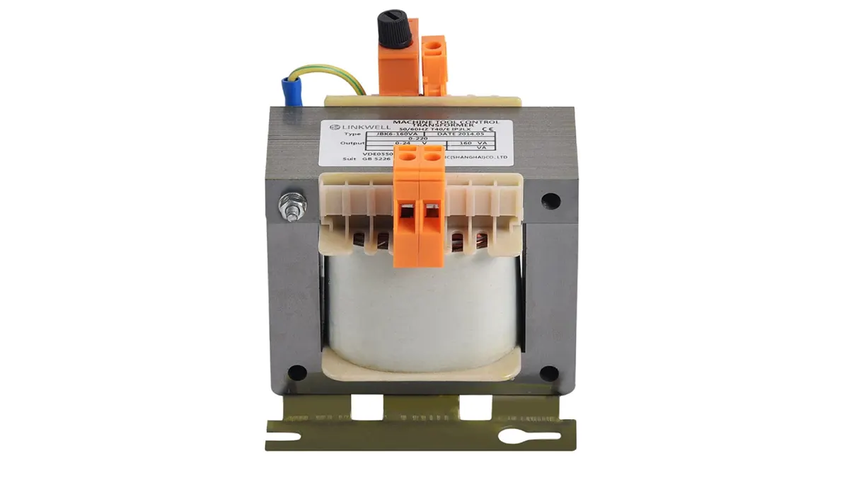
Control transformers are essential components in electrical systems, primarily used to step down voltage for control circuits. A fundamental aspect of their design is the number of primary windings they possess, which directly influences their functionality and application. Understanding this characteristic is key to selecting the appropriate transformer for a given task.
Typically, control transformers are designed with a single primary winding. This winding is connected to the main power source and is responsible for receiving the input voltage. The interaction between this primary winding and one or more secondary windings facilitates the voltage transformation required for the control circuit’s operation.
What Are the Primary Windings in Control Transformers

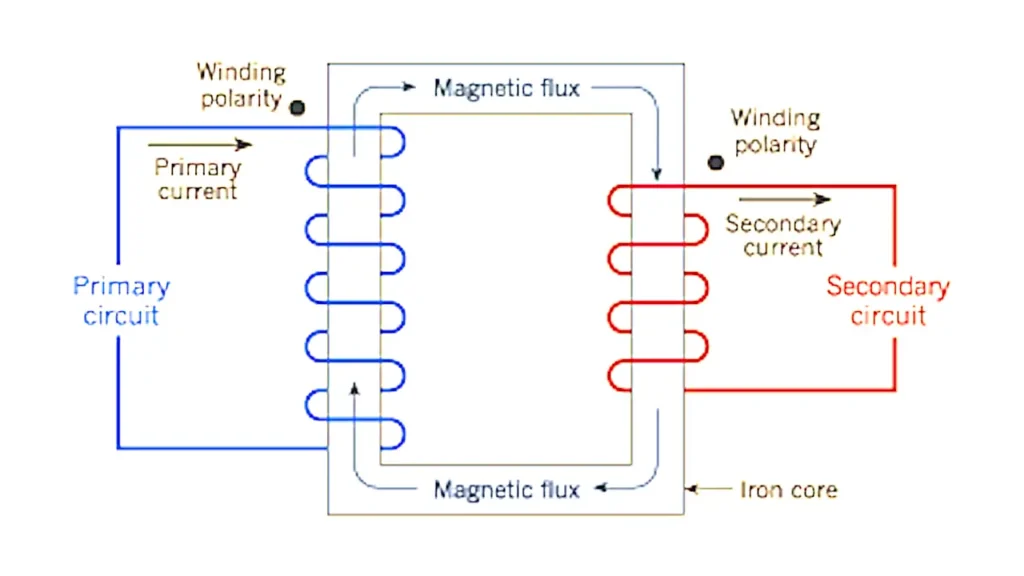
The primary windings in control transformers are the input side of the transformer. They are the coils of wire that are connected to the source of the alternating current (AC) power. When AC electricity flows through the primary windings, it creates a changing magnetic field within the transformer’s core. This fluctuating magnetic field is the fundamental principle that allows the transformer to function.
The primary winding’s characteristics, such as the number of turns of wire, are crucial in determining the transformer’s voltage transformation ratio. The relationship between the number of turns in the primary winding and the secondary winding dictates whether the transformer will step down (reduce) or step up (increase) the voltage. In control transformers, the primary winding typically has more turns than the secondary winding to achieve the desired lower output voltage for control circuits.
How Many Primary Windings Do Control Transformers Have
Control transformers are essential components in electrical systems, primarily used to step down voltage to safer levels for control circuits. A key aspect of their design is the configuration of their windings, which dictates how they transform electrical energy. Let’s delve into the specifics of primary windings in these devices.
Typical Configuration
In most standard control transformers, there is generally one primary winding. This winding is connected to the incoming power source and is responsible for receiving the initial AC voltage. The alternating current flowing through this primary winding generates a magnetic field within the transformer’s core, which then induces a voltage in the secondary winding(s).
Specialized Designs
While the vast majority of control transformers utilize a single primary winding, some specialized designs might incorporate multiple taps on the primary winding. These taps allow for adjustments to the input voltage, providing flexibility in situations where the supply voltage may vary. However, it’s important to note that these taps are still part of a single primary winding, rather than separate, distinct primary windings.
Three-Phase Transformers
Three-phase control transformers, which are used in applications with three-phase power, have three primary windings. Each of these windings is connected to one of the three phases of the incoming power supply. These primary windings work together to create a rotating magnetic field, which then induces a corresponding three-phase voltage in the secondary windings.
| Transformer Type | Number of Primary Windings |
| Single-Phase | One |
| Three-Phase | Three |
| Standard | One |
| With Voltage Taps | One (with taps) |
Why Are Two of the Primary Leads Crossed on a Control Transformer?
Crossing two of the primary leads on a control transformer is a specific wiring technique typically employed with dual-voltage primary transformers. These transformers are designed to be connected to two different input voltages, often 240V and 480V (in the US). The primary winding is actually split into two equal sections.
By connecting these two primary sections in series, the transformer is configured for the higher voltage (e.g., 480V). In this series configuration, the voltage is divided across both sections. To configure the transformer for the lower voltage (e.g., 240V), the two primary sections are connected in parallel. Crossing two of the primary leads is the specific wiring method to achieve this parallel connection, allowing each primary section to receive the full lower voltage.
Here’s a breakdown:
- Series Connection (Higher Voltage): The primary windings are connected end-to-end, so the total voltage is the sum of the voltage across each winding.
- Parallel Connection (Lower Voltage): Crossing specific primary leads allows the windings to be connected side-by-side, so each winding receives the full input voltage, enabling operation at the lower voltage rating of the transformer.
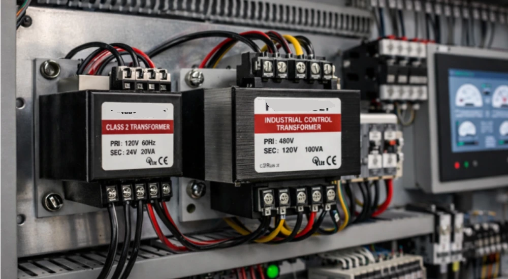
Why Do Control Transformers Usually Have Two Primary Coils
Control transformers commonly feature two primary coils to provide flexibility in accommodating different input voltage levels. This design allows the transformer to be easily configured for either a higher or a lower primary voltage by connecting the two coils in series or parallel, respectively. This adaptability makes a single transformer model suitable for a wider range of installations and power supply systems.
Here’s why this dual-primary coil configuration is beneficial:
- Dual Voltage Capability: By having two separate primary coils, the transformer can be wired to accept two different input voltages. For instance, a transformer might have two 120V primary coils. These can be connected in parallel for a 120V supply or in series for a 240V supply.
- Increased Versatility: This dual-voltage capability simplifies inventory and logistics, as a single transformer can serve applications with varying voltage standards. Installers can adapt to the specific site voltage without needing a different transformer model.
What Kind of Windings Do Control Transformers Tend to Have?
Control transformers typically tend to have windings made of either copper or aluminum. Copper is favored for its excellent electrical conductivity and ductility, allowing for tighter and more efficient winding. While aluminum offers a more cost-effective alternative, it has lower conductivity and requires a larger wire gauge for the same current-carrying capacity. Both materials are usually insulated with enamel or other suitable materials to prevent short circuits between the turns of the winding.
The configuration of these windings in control transformers often involves a primary winding designed for the higher input voltage and one or more secondary windings to provide the lower control voltage(s). Single-phase control transformers commonly have two primary coils that can be connected in series or parallel to accommodate different input voltages, as discussed previously. Three-phase control transformers will have three primary windings and three secondary windings to handle the three-phase power.
The specific type of winding used (e.g., helical, layer, disc) can vary depending on the transformer’s power rating, voltage requirements, and intended application. However, the fundamental principle remains the electromagnetic induction between the primary and secondary windings, facilitated by the core material, to step down the voltage to the desired control level.
Which Side of a Transformer Has More Windings?
The side of a transformer that has more windings depends entirely on whether the transformer is designed to step down or step up the voltage.
In a step-down transformer, which is common for control transformers reducing a higher voltage to a lower control voltage, the primary side has more windings than the secondary side. This is because the voltage is directly proportional to the number of turns in the winding. To achieve a lower output voltage, the secondary winding has fewer turns.
Conversely, in a step-up transformer, the secondary side has more windings than the primary side to increase the voltage. However, control transformers are predominantly used to step down voltage for control circuits, making them primarily step-down transformers.
How to Identify Primary and Secondary Winding of a Transformer?
To identify the primary and secondary windings of a transformer, you can look for several physical and electrical characteristics. Often, the manufacturer will provide clear markings on the transformer terminals or a datasheet indicating which side is the primary (input) and which is the secondary (output). If such markings are absent, you can often deduce the windings based on wire thickness and resistance.
Here are some common methods to identify the primary and secondary windings:
- Wire Gauge: In step-down transformers (where primary voltage is higher than secondary), the primary winding typically uses thinner wire than the secondary winding. This is because the primary side carries lower current. Conversely, the secondary side has thicker wire to handle the higher current at the lower voltage.
- Resistance Measurement: Using a multimeter set to measure resistance (ohms), you can often differentiate the windings. The primary winding, having more turns of thinner wire, will generally exhibit a higher DC resistance compared to the secondary winding, which has fewer turns of thicker wire. However, this method is most reliable for power transformers and might not be as distinct in smaller control transformers.
How Are the Primary Windings Connected When the Transformer is to Be Operated on a 480-Volt System
When a control transformer with dual primary windings (designed for, say, 240V and 480V operation) is to be operated on a 480-volt system, the primary windings are connected in series. This configuration effectively doubles the voltage rating of the primary side.
Each of the two primary windings is designed to handle 240 volts independently. By connecting them in series, the total voltage capacity of the primary side becomes the sum of the individual winding capacities, thus accommodating the 480-volt input.
In a series connection, the end of one primary winding is connected to the beginning of the other. The 480-volt power source is then connected across the remaining two terminals of the primary windings. This arrangement ensures that the 480-volt potential difference is distributed across both primary windings, with each winding experiencing approximately 240 volts, which is within their design specification. This prevents overvoltage and ensures the safe and efficient operation of the transformer.
Conclusion
Control transformers typically feature a single primary winding, designed to receive the input voltage. This primary winding then induces a voltage in one or more secondary windings, providing the necessary lower voltage for control circuits. While some specialized designs might incorporate multiple taps on the primary for voltage adjustments, the fundamental configuration usually involves one primary winding.
Understanding this basic design is crucial for properly selecting and implementing control transformers in various applications. The single primary winding efficiently facilitates the voltage step-down required for safe and reliable operation of control components. For businesses seeking tailored solutions, custom wholesale control transformers can be obtained from specialized suppliers.
Opting for custom wholesale control transformers allows for the specification of precise voltage ratios, power ratings, and other features to meet unique application demands. This ensures optimal performance and seamless integration within complex electrical systems. Contact us for your specific custom control transformer needs.