Welcome to our guide on properly sizing a control transformer, a crucial step in ensuring the reliable operation of your control circuits. Selecting the correct transformer capacity prevents overloading, voltage drops, and potential equipment damage, ultimately contributing to system efficiency and longevity. This blog will walk you through the essential factors and calculations involved in determining the appropriate VA rating for your specific application.
Accurately sizing a control transformer requires a thorough understanding of the power demands of all connected control devices. We’ll explore how to calculate the total volt-amperes (VA) required, considering both steady-state and inrush currents. By following these guidelines, you can confidently choose a control transformer that meets your system’s needs and guarantees optimal performance.
What is a Control Transformer
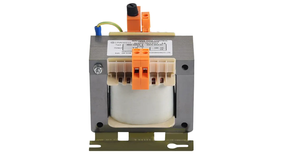
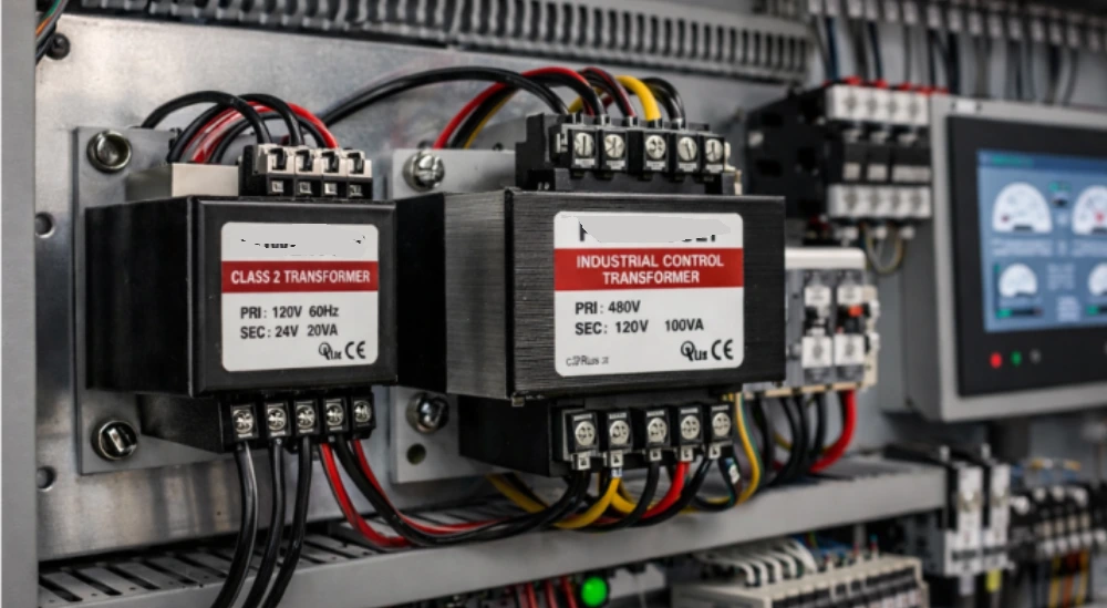
A control transformer is a specialized type of isolation transformer designed to provide a stable and reduced voltage to control circuits, typically found in industrial and commercial applications.
It steps down a higher voltage (like 240V or 480V) to a lower, safer voltage (often 24V or 120V) required for operating relays, contactors, timers, and other control components, ensuring reliable and safe operation of machinery and automated systems.
How to Size a Control Transformer?
Properly sizing a control transformer is vital for ensuring the reliable and safe operation of your control circuits. Selecting a transformer with inadequate capacity can lead to overheating, voltage drops, and premature failure, while an oversized transformer can be unnecessarily expensive and inefficient. Here’s a 5-step guide to correctly sizing your control transformer.
Step 1: Determine the Total VA of the Control Circuit
The first crucial step in sizing a control transformer is to determine the total volt-amperes (VA) required by all the components connected to the secondary side of the transformer. This involves identifying each device (e.g., relays, solenoids, pilot lights) and noting its individual VA rating. For resistive loads, the VA is equal to the wattage. For inductive loads, such as solenoids and motor starters, the VA rating is usually provided on the device’s nameplate and is often higher than the actual power (wattage) due to the reactive component of the load.
To calculate the total VA, simply sum the VA ratings of all simultaneously operating devices in the control circuit. It’s essential to consider the maximum VA each device can draw under normal operating conditions. If the VA rating isn’t directly provided, you can calculate it using the formula: VA = Voltage (V) x Current (A). Ensure you are using the secondary voltage of the transformer for these calculations.
Step 2: Account for Inrush Current
Inductive loads, such as motor starters, solenoids, and some relays, often draw a significantly higher current, known as inrush current, when they are initially energized. This inrush current can be several times their steady-state operating current and lasts for a brief period (typically a few cycles). Failing to account for inrush current can lead to voltage sag and potential failure of the control transformer to properly energize the loads.
To accommodate inrush current, it’s a common practice to apply a multiplier to the total steady-state VA calculated in the previous step. The appropriate multiplier depends on the type and quantity of inductive loads. For circuits with a significant number of inductive devices, a multiplier of 2 to 4 or even higher might be necessary. Consult the specifications of the inductive devices for their inrush current requirements or use industry guidelines to estimate an appropriate multiplier.
Step 3: Apply a Safety Factor
After calculating the total VA, including an allowance for inrush current, it’s prudent to apply a safety factor when selecting the control transformer’s VA rating. A common safety factor is to choose a transformer with a VA rating that is at least 20% to 25% higher than the calculated total VA. This safety margin provides a buffer for unexpected load increases, voltage fluctuations, and helps to prolong the life of the transformer by preventing it from operating at its maximum capacity continuously.
Applying a safety factor also helps to improve voltage regulation under load. When a transformer is operating close to its maximum rating, the output voltage can drop more significantly when loads are applied. A larger transformer operating below its full capacity will typically exhibit better voltage regulation, ensuring that the control devices receive the required voltage for proper operation.
Step 4: Consider Future Expansion
When sizing a control transformer, it’s also wise to consider potential future expansion of the control system. If there’s a possibility of adding more control devices in the future, selecting a transformer with some extra capacity now can save the cost and effort of replacing an undersized transformer later. Estimating potential future load increases and incorporating that into the safety factor can be a practical approach.
By anticipating future needs, you can avoid the inconvenience of having to upgrade your control transformer if new components are added to the system. This forward-thinking approach ensures that your control system has sufficient power capacity to accommodate future modifications without compromising performance or reliability.
Step 5: Select the Standard VA Rating
Control transformers are typically available in standard VA ratings. After calculating the required VA with the inrush multiplier and safety factor, you will likely need to select the next standard size up from your calculated value. For example, if your calculation yields 75 VA, you would typically choose the next standard size, such as 100 VA. Consulting supplier catalogs or industry standards will provide a list of available standard VA ratings for control transformers.
Choosing the next standard size ensures that you have adequate capacity for your current and potential future needs. While it might seem economical to choose a transformer with a VA rating very close to your calculated value, the small additional cost for the next standard size up is a worthwhile investment for improved reliability and flexibility.
What Are Standard Control Transformer Sizes
Standard control transformers are available in a range of volt-ampere (VA) ratings to suit various control circuit power requirements. These standard sizes provide engineers and technicians with readily available options for common applications, simplifying the selection and procurement process. The specific standard sizes offered can vary slightly between manufacturers, but there are common values widely recognized in the industry.
These standard VA ratings typically progress in a somewhat logarithmic fashion, offering finer granularity at lower power levels and larger steps at higher power levels. This allows for efficient matching of transformer capacity to the load demands of different control systems. Common standard sizes cater to a broad spectrum of applications, from small pilot control circuits to larger industrial automation systems.
Here are some common standard control transformer VA ratings:
- 25 VA
- 50 VA
- 75 VA
- 100 VA
- 150 VA
- 200 VA
- 250 VA
- 350 VA
- 500 VA
- 750 VA
- 1000 VA
- 1500 VA
- 2000 VA
- 3000 VA
- 5000 VA
Control Transformer Sizing Factors

Several key factors must be carefully considered when determining the appropriate size for a control transformer to ensure optimal performance and longevity of the connected control system. These factors primarily revolve around the power demands of the secondary circuit and the characteristics of the loads. Overlooking any of these aspects can lead to operational issues or premature transformer failure.
The main control transformer sizing factors include:
- Total Volt-Ampere (VA) of the Control Circuit: This is the fundamental starting point and involves summing the VA ratings of all devices that will be simultaneously powered by the transformer’s secondary winding. Accurate calculation of the steady-state VA is crucial to meet the continuous power requirements of the control system’s components.
- Inrush Current of Inductive Loads: Many control devices, such as relays, solenoids, and motor starters, exhibit a significantly higher current draw upon initial energization compared to their steady-state current. This inrush current must be accounted for to prevent voltage drops and ensure the transformer can reliably start these loads. An appropriate multiplier, based on the type and number of inductive devices, is typically applied to the total VA to accommodate inrush.
- Safety Factor: It’s a common and prudent practice to include a safety margin when selecting a control transformer’s VA rating. Choosing a transformer with a VA rating 20-25% higher than the calculated demand provides a buffer for unexpected load increases, voltage fluctuations, and contributes to better voltage regulation under load, ultimately extending the transformer’s lifespan.
- Future Expansion: Anticipating potential additions to the control circuit is another important sizing consideration. Selecting a transformer with some extra capacity initially can prevent the need for a costly and disruptive replacement if more devices are added to the system in the future.
- Environmental Conditions: While not directly a “power” factor, the ambient temperature and installation environment can affect a transformer’s performance. Transformers have thermal limitations, and operating in high ambient temperatures may require derating the transformer’s VA capacity to prevent overheating and ensure reliable operation.
How to Choose a Suitable Control Transformer Sizing
Selecting the right size for a control transformer involves a careful assessment of the power demands of your control circuit, including both steady-state and inrush currents. Applying a safety factor and considering future expansion are also crucial steps to ensure reliable and efficient operation.
Determine Total VA Requirement
Begin by calculating the total volt-amperes (VA) needed by summing the VA ratings of all devices connected to the transformer’s secondary side that will operate simultaneously. For resistive loads, VA equals watts, while for inductive loads, use the VA rating from the device’s nameplate, as it accounts for reactive power. Accurate determination of this base load is the foundation of proper sizing.
Account for Inrush Current
Inductive components like solenoids and motor starters draw a significantly higher inrush current upon initial energization. Multiply the VA of these inductive loads by an appropriate inrush factor (typically 2-4 or higher, depending on the device type) and add this to the total steady-state VA. This ensures the transformer can handle the momentary peak demand without excessive voltage drop.
Apply a Safety Margin
To ensure reliable operation and prolong the transformer’s life, apply a safety factor of 20-25% to the total VA calculated after accounting for inrush. This buffer accommodates unexpected load increases, voltage fluctuations, and provides better voltage regulation under load, preventing the transformer from operating at its maximum capacity continuously.
Consider Future Loads
Anticipate any potential future additions to the control circuit. If expansion is likely, factor in the estimated VA of these new devices when selecting the transformer size. Choosing a slightly larger transformer now can prevent the need for a costly replacement later when the system’s power requirements increase.
How Do I Calculate What Size Transformer I Need

Selecting the right size for a control transformer involves a careful assessment of the power demands of your control circuit, including both steady-state and inrush currents. Applying a safety factor and considering future expansion are also crucial steps to ensure reliable and efficient operation.
Step 1: Determine Total VA Requirement
Begin by calculating the total volt-amperes (VA) needed by summing the VA ratings of all devices connected to the transformer’s secondary side that will operate simultaneously. For resistive loads, VA equals watts, while for inductive loads, use the VA rating from the device’s nameplate, as it accounts for reactive power. Accurate determination of this base load is the foundation of proper sizing.
Step 2: Account for Inrush Current
Inductive components like solenoids and motor starters draw a significantly higher inrush current upon initial energization. Multiply the VA of these inductive loads by an appropriate inrush factor (typically 2-4 or higher, depending on the device type) and add this to the total steady-state VA. This ensures the transformer can handle the momentary peak demand without excessive voltage drop.
Step 3: Apply a Safety Margin
To ensure reliable operation and prolong the transformer’s life, apply a safety factor of 20-25% to the total VA calculated after accounting for inrush. This buffer accommodates unexpected load increases, voltage fluctuations, and provides better voltage regulation under load, preventing the transformer from operating at its maximum capacity continuously.
Step 4: Consider Future Loads
Anticipate any potential future additions to the control circuit. If expansion is likely, factor in the estimated VA of these new devices when selecting the transformer size. Choosing a slightly larger transformer now can prevent the need for a costly replacement later when the system’s power requirements increase.
What Will Happen if an Undersized Transformer is Installed in a Control System?
Installing an undersized transformer in a control system can lead to several detrimental effects due to the transformer being unable to supply the necessary power to the connected loads. This can result in operational issues, reduced lifespan of the transformer, and potential damage to the control system components.
Here’s what can happen:
- Overheating: The transformer will draw excessive current trying to meet the load demands, leading to overheating of the windings and core. This can degrade the insulation, causing premature failure of the transformer.
- Voltage Drop: The output voltage will sag significantly under load, potentially causing control devices to malfunction or operate erratically. Relays might chatter, contactors may not fully engage, and electronic components could receive insufficient power.
- Reduced Lifespan: Continuous operation above the transformer’s rated capacity will significantly shorten its operational life. The thermal stress on the insulation materials accelerates their degradation.
- System Instability: The inconsistent and insufficient power supply can lead to unpredictable behavior of the control system, causing intermittent failures and unreliable operation of the machinery or process being controlled.
- Potential Damage to Loads: Some control components are sensitive to undervoltage conditions and prolonged operation outside their voltage specifications can lead to their damage or failure.
Conclusion
In conclusion, properly sizing a control transformer is crucial for ensuring the reliable and safe operation of control circuits. Accurately calculating the total VA demand of all connected devices, considering inrush currents, and applying appropriate safety margins are essential steps in this process. An undersized transformer can lead to overheating and failure, while an oversized one can be unnecessarily costly.
By carefully assessing the specific requirements of your application, you can select a control transformer that meets the power demands without compromising efficiency or longevity. Factors like the type of load and potential future expansion should also be taken into account during the sizing process. For businesses seeking tailored solutions, custom wholesale control transformers can be obtained from specialized suppliers.
Opting for custom wholesale control transformers allows for the specification of precise VA ratings and other features to perfectly match your unique needs. This ensures optimal performance, efficient power delivery, and long-term cost-effectiveness. Contact us for your specific custom control transformer requirements.