Welcome to the ultimate guide on how to wire a junction box! Whether you’re a seasoned electrician or a homeowner tackling a DIY project, understanding the proper techniques for wiring these essential components is crucial for safety and functionality within your electrical system in the United States. This comprehensive guide will walk you through the necessary steps to ensure secure and compliant connections every time.
From identifying the wires to making the final connections and safely closing the box, we’ll cover the key aspects of junction box wiring relevant to US electrical practices. By following these guidelines, you’ll gain the confidence and knowledge to handle various wiring scenarios effectively, ensuring a reliable and safe electrical installation in your home or workspace. Let’s dive in and master the art of wiring a junction box!
What Is Junction Box Wiring
Junction box wiring refers to the process of making electrical connections within a junction box, which is a protective enclosure required by the National Electrical Code (NEC) in the United States for all wire splices and terminations. This involves carefully joining wires together using appropriate connectors, such as wire nuts or terminal blocks, ensuring secure and electrically sound connections. Proper wiring within a junction box is crucial for distributing power safely and effectively to various electrical devices and fixtures throughout a building.
The primary goal of junction box wiring is to create reliable electrical pathways while protecting these connections from environmental factors and accidental contact. This includes correctly identifying and connecting hot, neutral, and ground wires according to their color-coding and the specific requirements of the circuit. Furthermore, the NEC mandates that all wiring within a junction box must be contained within the enclosure and the box must be accessible, ensuring safety and facilitating future inspection or maintenance of the electrical system.
Junction Box Used for Commercial and Industrial Applications

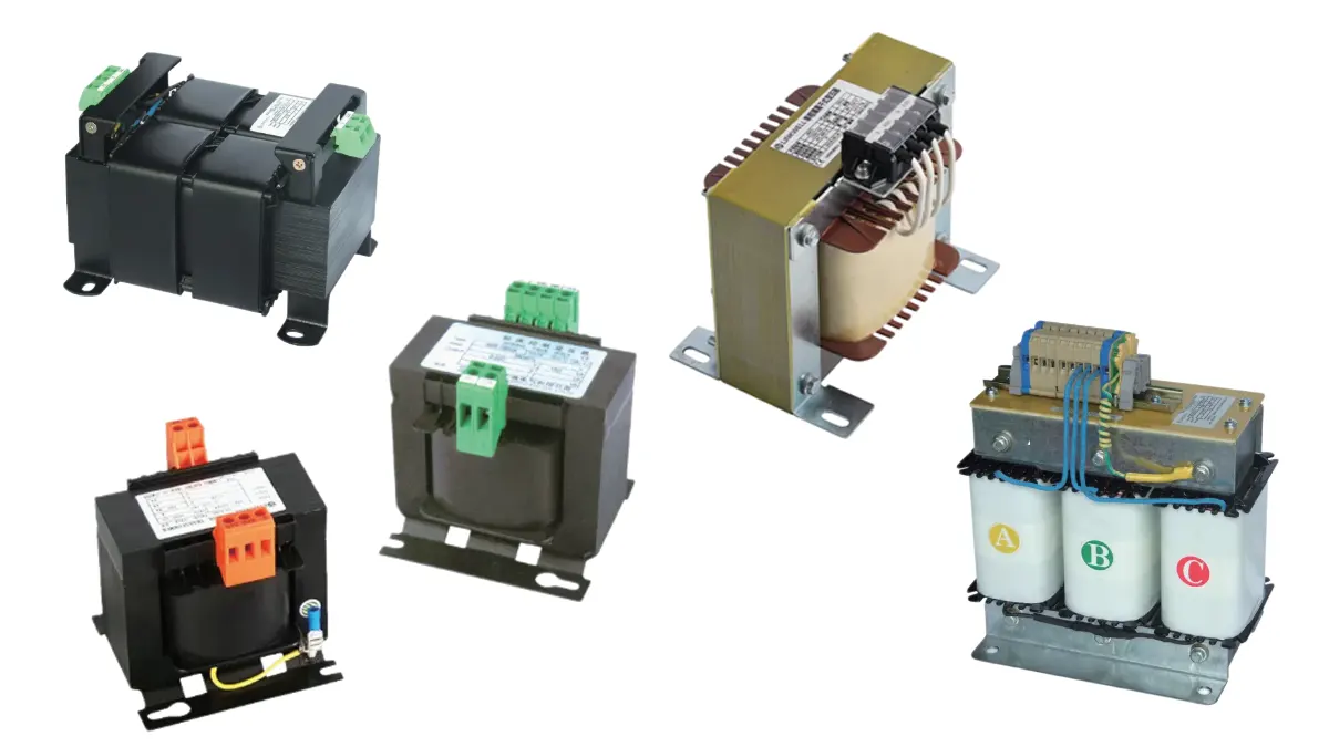
Junction boxes designed for commercial and industrial applications are not simple wiring enclosures. They function as integrated electrical panel housings that support complex power distribution, control, and automation systems. These junction boxes are widely used in factories, commercial buildings, data centers, automation lines, and electrical control rooms, where reliability and scalability are critical.
Inside the enclosure, components are systematically arranged to ensure safety, efficiency, and ease of maintenance. DIN rails are commonly used to mount terminal blocks, circuit breakers, relays, contactors, and PLC modules in a standardized layout. Cable management systems, such as wiring ducts and tie points, keep conductors organized, reducing installation errors and improving airflow. For heat-sensitive equipment, cooling fans or filter fans are often integrated to maintain stable internal temperatures and extend component lifespan.
These junction boxes are typically made from steel or industrial-grade plastics and comply with international standards such as IEC and UL. Their modular structure allows future expansion, making them ideal for evolving industrial electrical systems.
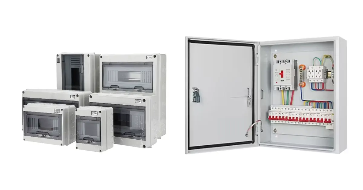
Junction Box Used for Outdoor and Renewable Modular Systems

Junction boxes used in outdoor and renewable modular systems serve as robust electrical hubs rather than simple connection points. They are commonly applied in solar power systems, wind energy installations, EV charging infrastructure, outdoor automation units, and distributed energy networks, where environmental protection and system stability are essential.
These enclosures house complete electrical panel assemblies, including DIN rails for mounting terminal blocks, surge protection devices, fuses, and monitoring modules. Advanced cable management systems ensure orderly routing of power and signal cables, minimizing electromagnetic interference and simplifying maintenance. Due to outdoor exposure and high thermal loads, many designs incorporate cooling fans, ventilation systems, or heat dissipation structures to control internal temperatures and protect sensitive components.
Constructed from UV-resistant plastics or corrosion-resistant metal, these junction boxes feature high IP ratings for water, dust, and weather protection. Their modular and scalable design supports fast installation and reliable operation in modern renewable energy and outdoor electrical systems.
How to Wire a Junction Box
Understanding proper junction box wiring is a fundamental skill for anyone working with electrical systems in the United States. Adhering to the National Electrical Code (NEC) guidelines is paramount to ensure safety and functionality.
This guide will walk you through the essential steps involved in junction box wiring, providing detailed explanations to help you perform the task correctly and safely in accordance with US electrical practices.
Step 1: Ensuring Safety First
Before commencing any junction box wiring, prioritizing safety is crucial. Always ensure that the power to the circuit you will be working on is completely turned off at the main electrical panel. Utilize a reliable voltage tester to confirm that the wires within the junction box are not live. In the United States, it is highly recommended to wear appropriate personal protective equipment (PPE), such as insulated gloves and safety glasses, to further minimize the risk of electrical shock or injury during the wiring process.
Familiarizing yourself with the specific requirements of the National Electrical Code (NEC) relevant to junction box wiring is also essential. The NEC outlines regulations regarding wire types, sizes, color-coding, and proper connection methods, all of which must be followed to ensure a safe and compliant installation in the US. Taking these preliminary safety measures and understanding the relevant codes are non-negotiable first steps in any electrical wiring endeavor.
Step 2: Identifying the Wires
Accurately identifying the different wires within the junction box is a critical step in ensuring correct and safe junction box wiring. In the United States, electrical wires are color-coded to indicate their function: black or red typically indicates hot (live) wires, white usually signifies neutral wires, and green or bare copper wires are for grounding. Carefully examine the wires and trace them back if necessary to understand their role in the circuit.
If you encounter any wires that are not color-coded or if you are unsure of their function, it is imperative to use a voltage tester to positively identify them after you have confirmed the power is off. Never assume the function of a wire based solely on its color, especially in older installations where wiring practices may not have been consistent with current US standards. Proper identification prevents incorrect connections, which can lead to malfunctions, damage to equipment, or even safety hazards.
Step 3: Making the Connections
The core of junction box wiring involves making secure and electrically sound connections between the appropriate wires. In the United States, common methods for joining wires include using wire connectors (often called wire nuts) or terminal blocks. When using wire nuts, strip the insulation from the ends of the wires, twist the bare conductors together clockwise, and then screw the wire nut firmly onto the twisted wires, ensuring no bare wire is exposed outside the connector.
For terminal blocks, strip the wire ends and securely fasten them into the designated terminals using a screwdriver. It is crucial to ensure that all connections are tight to prevent loose wires, which can cause arcing, overheating, and potential fire hazards. Always connect wires of the same function together (hot to hot, neutral to neutral, ground to ground) unless the specific wiring diagram for your application indicates otherwise. Adhering to these proper connection techniques is vital for a safe and reliable electrical system in the US.
Step 4: Grounding the System
Proper grounding is a fundamental safety aspect of junction box wiring in the United States, designed to provide a safe path for fault currents and help prevent electric shock. Typically, all ground wires (green or bare copper) entering the junction box should be connected. If the junction box is metal, these ground wires must also be connected to the metal box itself using a grounding screw or a grounding clip.
For non-metallic junction boxes, the ground wires should still be connected, and a separate ground wire should be run to any grounding terminal on a device or fixture being connected. Ensuring a continuous and effective grounding path throughout the electrical system is a critical requirement of the National Electrical Code (NEC) in the US and is essential for the safety of the installation and its users.
Step 5: Organizing Wires and Securing Connections
After making all the necessary electrical connections, the next step in junction box wiring is to carefully organize the wires within the box. Gently fold the connected wires into the box, ensuring they are not overly crowded or pinched. This helps to prevent damage to the insulation and makes it easier to install the cover without putting stress on the connections.
If the junction box has internal clamps or connectors for the incoming cables or conduits, ensure these are tightened to secure the wires and prevent them from being accidentally pulled out. A well-organized junction box not only promotes safety but also makes future troubleshooting or modifications easier. Secure connections and neatly arranged wires are hallmarks of professional and compliant electrical work in the United States.
Step 6: Installing the Junction Box Cover
The final step in junction box wiring is to install the appropriate cover securely onto the box. The cover serves as a physical barrier, protecting the wire connections from damage and preventing accidental contact with live wires, as mandated by the National Electrical Code (NEC) in the United States. Ensure that the cover fits properly and is fastened tightly with the screws provided.
For outdoor or damp locations, use a weatherproof cover and ensure any gaskets or seals are correctly installed to prevent moisture from entering the box. A properly installed cover is essential for the overall safety and integrity of the electrical installation, providing a finished and code-compliant enclosure for the wired connections.
How to Wire 3 Way Junction Box
Wiring a 3-way junction box might seem complex, but it’s a fundamental skill for controlling a single light fixture from two different switch locations in your US home. This setup involves specific wiring configurations and understanding the role of traveler wires. By following these steps carefully and adhering to the National Electrical Code (NEC) prevalent in the United States, you can successfully wire a 3-way junction box.
Step 1: Ensuring Power is Off and Safety Precautions
Before commencing any wiring, your absolute priority is safety. You must locate the circuit breaker that controls the power to the light fixture and the switch locations you’ll be working on and turn it off completely. To ensure the power is indeed off, use a reliable voltage tester on all wires within the junction boxes at both the light fixture and the switch locations. Wearing appropriate personal protective equipment (PPE), such as insulated gloves and safety glasses, is also highly recommended throughout this process to minimize any potential risk of electrical shock.
Step 2: Identifying the Existing Wiring
Carefully examine the wires present in each of the junction boxes: the one for the light fixture and the two for the switches. In a typical 3-way switch setup in the US, you’ll likely find a power source entering one switch box, a set of traveler wires running between the two switch boxes, and a switched hot wire going from the second switch box to the light fixture. Identify the hot (usually black), neutral (usually white), and ground (usually green or bare copper) wires in each box. Pay close attention to any existing 3-wire cables (typically black, white, red, and a bare ground) as these often carry the traveler wires.
Step 3: Wiring the First 3-Way Switch
In the first switch box, you’ll typically connect the incoming power. The hot wire from the power source will connect to the common terminal of the 3-way switch (usually a darker screw, often labeled “common”). The neutral wire from the power source will usually be passed through this box, often connected to other neutral wires going to other devices or the light fixture. The ground wire from the power source should be connected to the ground terminal on the switch and any other ground wires in the box, ensuring a continuous ground path as per NEC requirements in the US. The two remaining terminals on the 3-way switch are for the traveler wires, which will run to the second switch.
Step 4: Wiring the Second 3-Way Switch
In the second switch box, you’ll connect the traveler wires coming from the first switch and the wire going to the light fixture. The two traveler wires should be connected to the two traveler terminals on this 3-way switch (the two screws that are not the common terminal). The common terminal on this second 3-way switch will be connected to the switched hot wire that runs to the light fixture. Ensure all connections are secure using appropriate wire connectors, and the ground wire in this box is connected to the ground terminal on the switch and any other ground wires present, maintaining the ground path.
Step 5: Wiring the Light Fixture Junction Box
In the light fixture junction box, you’ll typically have the neutral wire coming from the power source (often passing through one of the switch boxes) and the switched hot wire coming from the common terminal of the second 3-way switch. Connect the white (neutral) wire to the neutral terminal on the light fixture. Connect the black (switched hot) wire to the hot terminal on the light fixture. Finally, connect the ground wire (green or bare copper) to the grounding terminal on the light fixture and ensure it’s connected to any other ground wires in the box, completing the grounding for the fixture as required by US electrical codes.
Step 6: Testing the Operation
After you have carefully wired all the connections and ensured all wires are securely fastened and the junction boxes are properly covered, you can carefully turn the power back on at the circuit breaker. Test the operation of the 3-way switches by flipping each switch individually. The light fixture should turn on or off regardless of the position of the other switch. Test both switches to ensure they can independently control the light. If the wiring is incorrect, the light might not function as expected, or you might trip the circuit breaker, indicating a wiring error that needs to be investigated with the power off.
Step 7: Final Inspection and Securing
Once you have confirmed that the 3-way switches are operating correctly, perform a final inspection of all the junction boxes. Ensure that all wire connections are secure, wires are neatly tucked into the boxes without being pinched, and all junction box covers are properly installed and fastened. This final step ensures a safe and compliant installation according to the National Electrical Code (NEC) standards prevalent in the United States.
How to Wire a 4 Way Junction Box
Wiring a 4-way junction box introduces a level of complexity beyond standard 3-way setups, typically arising when you need to control a single light fixture from three or more switch locations in your US home. This configuration necessitates the use of specialized 4-way switches in conjunction with a pair of 3-way switches. Understanding the unique wiring pathways and the role of the additional 4-way switches is key to a successful and safe installation that complies with the National Electrical Code (NEC).
Step 1: Absolute Power Disconnection and Verification
Before you even think about touching any wires, your paramount concern must be safety. Locate the circuit breaker in your electrical panel that supplies power to the light fixture and all the intended switch locations. Flip this breaker to the “off” position. Crucially, you must then use a reliable voltage tester at each junction box involved – the light fixture box and all the switch boxes – to absolutely confirm that no wires are live. Donning appropriate personal protective equipment (PPE), such as insulated gloves and safety glasses, provides an essential additional layer of protection against potential electrical hazards.
Step 2: Mapping the Existing and Planned Wiring
Carefully assess the wiring present in each junction box. In a 4-way switch circuit in the US, you’ll generally find the main power source entering one of the 3-way switch boxes. From there, a 3-wire cable (containing travelers) runs to the first 4-way switch. Another 3-wire cable then connects this 4-way switch to the next 4-way switch (if more than three control points are needed), and finally, a 3-wire cable runs from the last 4-way switch to the second 3-way switch. A 2-wire cable (switched hot and neutral) will then run from this second 3-way switch to the light fixture. Meticulously identify the hot (usually black), neutral (usually white), and ground (usually green or bare copper) wires in each box, paying particular attention to the red and black wires within the 3-wire cables that serve as travelers.
Step 3: Wiring the Initial 3-Way Switch (Power Source)
At the 3-way switch box where the main power enters, connect the incoming hot wire to the common terminal of the 3-way switch (the darker screw). The incoming neutral wire will typically bypass this switch box and continue towards the light fixture, often being wire-nutted with other neutral wires. The ground wire from the power source must be connected to the ground terminal on this 3-way switch and any other ground wires in the box, ensuring a continuous ground path as mandated by the NEC in the US. The two remaining terminals on this 3-way switch are for the traveler wires that will run to the first 4-way switch.
Step 4: Wiring the 4-Way Switches (Intermediate Control)
The 4-way switches, acting as the intermediate control points, have four terminals. The two traveler wires coming from one of the 3-way switches are connected to a pair of terminals on the 4-way switch. The other pair of terminals on this 4-way switch will connect to the two traveler wires going to the next switch in the sequence (either another 4-way or the final 3-way). It’s crucial to connect the travelers correctly – the incoming travelers go to one set of terminals, and the outgoing travelers go to the other set. Incorrect wiring here is a common source of malfunction. Ensure the ground wire in each 4-way switch box is connected to the ground terminal on the switch and any other grounds present.
Step 5: Wiring the Final 3-Way Switch (to Light Fixture)
At the second 3-way switch box, you’ll connect the traveler wires coming from the last 4-way switch and the wire going to the light fixture. The two traveler wires from the preceding switch are connected to the two traveler terminals on this 3-way switch (the screws that are not the common terminal). The common terminal on this second 3-way switch is then connected to the switched hot wire (usually black) that runs to the light fixture. The neutral wire (white) that originated from the power source (and likely passed through the first 3-way switch box) will also be present in this box, ready to continue to the light fixture. Ensure all connections are secure, and the ground wire is connected to the switch’s ground terminal and any other grounds.
Step 6: Wiring the Light Fixture Junction Box
In the light fixture junction box, you will connect the neutral wire (white) coming from the initial power source (via the switch boxes) to the neutral terminal on the light fixture. The switched hot wire (black) coming from the common terminal of the final 3-way switch is connected to the hot terminal on the light fixture. Finally, the ground wire (green or bare copper) must be connected to the grounding terminal on the light fixture and any other ground wires in the box, completing the grounding for the fixture as per NEC requirements in the US.
Step 7: Thorough Operational Testing
After meticulously checking all your wiring connections and ensuring all junction boxes are properly covered, carefully restore power at the circuit breaker. Test the operation of all the switches. The light fixture should turn on or off regardless of the position of any of the three (or more) switches. Systematically test every switch combination to confirm correct functionality. If the light doesn’t behave as expected or if the breaker trips, immediately turn off the power and re-examine your wiring at each junction box, paying close attention to the traveler wire connections at the 4-way switches.
Step 8: Final Inspection and Securement
Once you have verified the correct operation of the entire 4-way switching system, conduct a final, thorough inspection of all junction boxes. Double-check that all wire connections are tight, wires are neatly arranged within the boxes without any pinching or stress, and all junction box covers are securely installed and fastened. This final step is crucial for ensuring a safe, reliable, and code-compliant electrical installation in accordance with the National Electrical Code (NEC) standards applicable in the United States.
How to Wire a 220 Volt Junction Box
Wiring a 220-volt junction box in the United States requires careful attention to safety and adherence to the National Electrical Code (NEC). 220-volt circuits power high-demand appliances and involve different wiring configurations than standard 120-volt circuits. Ensuring correct connections and proper grounding is paramount to prevent electrical hazards and ensure the appliance operates safely and efficiently.
Step 1: Prioritizing Safety and Power Disconnection
Before you begin any wiring on a 220-volt junction box, your safety is the absolute top priority. You must locate the correct double-pole circuit breaker in your main electrical panel that controls the 220-volt circuit you’ll be working on and switch it off completely. It is crucial to use a reliable voltage tester specifically rated for higher voltages to verify that all wires within the junction box are de-energized. Wearing appropriate personal protective equipment (PPE), such as insulated gloves and safety glasses, is essential to protect yourself from potential electrical shock or injury.
Step 2: Identifying the 220-Volt Wiring
Carefully examine the wires present in the 220-volt junction box. In the United States, a typical 220-volt circuit for a 3-wire setup will have two hot wires (usually black and red), a neutral wire (usually white), and a ground wire (usually green or bare copper). For a 4-wire setup, often required for appliances like dryers and ranges, you will have two hot wires, a neutral wire, and a separate ground wire. Correctly identifying each wire’s function is critical for proper and safe wiring of the 220-volt appliance.
Step 3: Connecting the Hot Wires
Connect the two hot wires from the 220-volt power source to the corresponding terminals of the appliance wiring within the junction box. Typically, these will be connected using appropriately sized wire connectors or terminal blocks designed for the voltage and amperage of the circuit. Ensure these connections are very secure, as loose connections can lead to overheating and potential fire hazards associated with high-power appliances.
Step 4: Connecting the Neutral Wire (If Applicable)
If your 220-volt circuit includes a neutral wire (often in 4-wire setups), connect the white neutral wire from the power source to the designated neutral terminal on the appliance wiring within the junction box. This connection is essential for appliances that also utilize 120-volt components or have specific neutral requirements. Ensure this connection is also secure.
Step 5: Connecting the Ground Wire
Proper grounding is absolutely critical for a 220-volt circuit in the United States to ensure safety in case of a fault. Connect the green or bare copper ground wire from the power source to the designated grounding terminal on the appliance wiring within the junction box. If the junction box itself is metal, ensure the ground wire is also connected to the metal box using a grounding screw or clip to ground the enclosure.
Step 6: Organizing Wires and Securing Connections
Carefully organize the connected wires within the 220-volt junction box, ensuring they are not overcrowded or pinched. Gently fold the wires into the box to allow for easy installation of the cover without putting stress on the connections. Ensure any cable clamps or connectors securing the wires entering the box are properly tightened.
Step 7: Installing the Junction Box Cover and Testing
Finally, securely install the appropriate cover onto the 220-volt junction box. This cover protects the connections and prevents accidental contact with the high-voltage wiring. After ensuring the cover is properly fastened, and only when you are certain all connections are correct and safe, you can carefully turn the double-pole circuit breaker back on at the main electrical panel and test the operation of the 220-volt appliance. If it doesn’t function correctly or if the breaker trips, immediately turn off the power and re-check your wiring.
How to Wire a Junction Box for a Socket
Wiring a junction box for a socket (electrical outlet or receptacle) in your US home is a common task that, when done correctly and in accordance with the National Electrical Code (NEC), provides safe and reliable power access. This process involves understanding the standard color-coding of wires and ensuring proper connections for the hot, neutral, and ground conductors within the junction box that will house the socket.
Step 1: Ensuring Complete Power Disconnection and Safety
Before you begin any wiring, your absolute priority is safety. Locate the circuit breaker in your electrical panel that controls the power to the area where you’ll be working and switch it to the “off” position. To be absolutely certain the power is disconnected, use a reliable voltage tester on all wires within the junction box where you will be installing the socket. It is highly recommended that you wear appropriate personal protective equipment (PPE), such as insulated gloves and safety glasses, throughout this process to protect yourself from any potential electrical hazards.
Step 2: Identifying the Incoming Wires
Carefully examine the wires entering the junction box where you intend to install the socket. In standard US residential wiring, you will typically find a 2-wire cable with ground (black, white, and bare copper or green) or a 3-wire cable with ground (black, red, white, and bare copper or green), depending on whether it’s part of a switch loop or a direct power feed. Identify the black wire (hot), the white wire (neutral), and the bare copper or green wire (ground). If there’s a red wire present, it might be a switched hot or part of a multi-wire branch circuit, requiring careful identification based on your specific wiring scenario.
Step 3: Connecting the Hot Wire to the Socket
Locate the brass-colored terminal screw(s) on the socket. These are designated for the hot wire. Take the black wire from the incoming cable in the junction box and, using a wire stripper, expose about 1/2 to 3/4 inch of bare conductor. Create a clockwise loop at the end of the bare wire and securely fasten it around one of the brass-colored terminal screws, tightening the screw firmly. If there are multiple hot wires in the box (e.g., feeding other outlets), they should be connected together with a wire connector (wire nut) and a pigtail (a short length of wire) should then run from this connection to the brass terminal of the socket.
Step 4: Connecting the Neutral Wire to the Socket
Locate the silver-colored terminal screw(s) on the socket. These are designated for the neutral wire. Take the white wire from the incoming cable in the junction box and, using a wire stripper, expose about 1/2 to 3/4 inch of bare conductor. Create a clockwise loop at the end of the bare wire and securely fasten it around one of the silver-colored terminal screws, tightening the screw firmly. Similar to the hot wires, if there are multiple neutral wires in the box, they should be connected together with a wire connector, and a pigtail should run from this connection to the silver terminal of the socket.
Step 5: Connecting the Ground Wire to the Socket and Box
Locate the green grounding screw on the socket. Take the bare copper or green ground wire from the incoming cable in the junction box and, using a wire stripper if needed, create a loop at the end. Securely fasten this loop around the green grounding screw on the socket, tightening the screw firmly. Additionally, if the junction box is made of metal, you must also connect the ground wire to the metal box itself using a grounding screw or a grounding clip to ensure the box is properly grounded, as required by the NEC in the US. All ground wires in the box should be connected together with a wire connector.
Step 6: Organizing Wires and Mounting the Socket
Carefully fold the connected wires into the junction box, ensuring they are not overly crowded or pinched. Gently position the socket into the box, aligning the screw holes. Securely fasten the socket to the junction box using the mounting screws provided with the receptacle. Ensure the socket sits flush against the wall or mounting surface.
Step 7: Installing the Cover Plate and Restoring Power
Once the socket is securely mounted, install the appropriate cover plate over the junction box and socket. This provides a finished look and protects the wiring and terminals. Ensure the cover plate is securely fastened with its screws. Only after the cover plate is in place and you have double-checked all your connections, you can carefully restore power at the circuit breaker in your electrical panel and test the newly installed socket with a known working device.
How to Wire a Junction Box for Lighting
Wiring a junction box for lighting in your US home is a common electrical task that, when executed correctly and in accordance with the National Electrical Code (NEC), ensures safe and reliable illumination. This process involves understanding the standard wire color-coding and making secure connections for the hot, neutral, and ground wires within the junction box that will serve as the mounting and connection point for your light fixture.
Step 1: Ensuring Absolute Power Disconnection and Safety
Before you commence any wiring work, your paramount concern must be safety. Locate the circuit breaker in your electrical panel that controls the power to the lighting circuit you’ll be working on and switch it completely to the “off” position. To absolutely verify that the power is disconnected, use a reliable voltage tester on all wires within the junction box where you will be installing the lighting fixture. It is strongly recommended that you wear appropriate personal protective equipment (PPE), such as insulated gloves and safety glasses, throughout this process to protect yourself from any potential electrical hazards.
Step 2: Identifying the Incoming and Fixture Wires
Carefully examine the wires present in the junction box and those extending from your light fixture. In standard US residential lighting circuits, you will typically find a 2-wire cable with ground (black, white, and bare copper or green) supplying power to the box. The light fixture will also have wires, typically black (hot), white (neutral), and a bare copper or green wire (ground). Correctly identifying each wire’s function is crucial for a safe and functional lighting installation.
Step 3: Connecting the Hot Wires
Locate the black wire from the power supply in the junction box and the black wire from your light fixture. These are the hot wires. Using a wire stripper, expose about 1/2 to 3/4 inch of bare conductor on the ends of both wires. Twist these bare ends together clockwise and then securely fasten them together with an appropriately sized wire connector (wire nut). Ensure that no bare wire is exposed outside the wire connector. If there are other hot wires in the junction box that need to be connected to the lighting circuit, they should also be joined in this connection.
Step 4: Connecting the Neutral Wires
Locate the white wire from the power supply in the junction box and the white wire from your light fixture. These are the neutral wires. Using a wire stripper, expose about 1/2 to 3/4 inch of bare conductor on the ends of both wires. Twist these bare ends together clockwise and then securely fasten them together with an appropriately sized wire connector (wire nut), ensuring no bare wire is exposed. If there are other neutral wires in the junction box that are part of the same circuit, they should also be included in this connection.
Step 5: Connecting the Ground Wires and Fixture Mounting
Locate the bare copper or green ground wire from the power supply in the junction box and the corresponding ground wire from your light fixture. Using a wire stripper if needed, twist these bare ends together clockwise and securely fasten them together with a wire connector (often a green one with a pre-drilled hole for a grounding screw). If the junction box is made of metal, you must also connect the ground wire to the metal box itself using a grounding screw or grounding clip to ensure the box is properly grounded, as required by the NEC in the US. After connecting the ground wires, carefully mount the light fixture to the junction box using the screws or mounting hardware provided with the fixture, ensuring a secure and stable attachment.
Step 6: Organizing Wires and Installing the Fixture Canopy
Carefully tuck the connected wires back into the junction box, ensuring they are not pinched or overly crowded. Gently position the canopy or base of the light fixture to cover the junction box and wiring. Secure the canopy to the mounting bracket or junction box using the screws or fasteners provided with the fixture, ensuring a snug and aesthetically pleasing fit against the ceiling or wall.
Step 7: Restoring Power and Testing the Light Fixture
Once the light fixture is securely mounted and the canopy is in place, and only after you have double-checked all your wire connections, you can carefully restore power at the circuit breaker in your electrical panel. Test the light fixture by turning on the corresponding switch to ensure it illuminates correctly. If the light does not turn on or if the circuit breaker trips, immediately turn off the power and re-check your wiring connections in the junction box and at the fixture.
Conclusion
Mastering the art of wiring a junction box, as outlined in this comprehensive guide, is a fundamental skill for anyone undertaking electrical work in the United States. By adhering to these steps and understanding the principles of safe and correct wiring, you ensure the integrity and safety of your electrical system, complying with established US standards and best practices. Proper wiring within junction boxes is crucial for preventing hazards and ensuring reliable electrical connections.
For businesses and contractors in the USA seeking tailored solutions, we offer wholesale custom junction boxes to meet your specific project needs. Our custom options allow for precise specifications in terms of size, material, and features, ensuring a perfect fit for your unique electrical applications. Partner with us to obtain high-quality, custom-designed junction boxes that streamline your installations and meet all relevant US regulations.
Ready to elevate your electrical projects with custom junction boxes? Contact us today to discuss your wholesale requirements and explore the possibilities of tailored solutions. Let us provide you with the perfect enclosures to ensure the safety and efficiency of your electrical systems across the United States.