Ensuring the reliability of dry-type transformers involves rigorous testing at various stages. Two primary testing environments exist: the factory, where comprehensive assessments are performed before shipment, and the field, where on-site evaluations are conducted after installation and during maintenance.
While both aim to verify the transformer’s integrity, the scope, equipment, and objectives of factory and field testing differ significantly. Understanding these distinctions is crucial for interpreting test results and maintaining the long-term health and performance of your dry-type transformer.
Dry Type Transformer Uses
Dry-type transformers find widespread application across numerous industries and settings due to their inherent safety and environmental benefits. Their versatility allows them to serve various crucial functions in electrical power systems, from stepping down or stepping up voltage levels to providing electrical isolation and ensuring the reliable operation of sensitive equipment. Their suitability for indoor and confined spaces further expands their utility in commercial, industrial, and residential environments.
Here are some common uses of dry-type transformers:
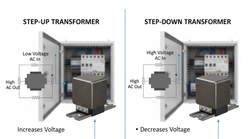
- Power Distribution: Stepping down high-voltage electricity from utility lines to lower voltages suitable for commercial and industrial use within buildings.
- Industrial Applications: Supplying power to machinery, control systems, and various industrial processes.
- Commercial Buildings: Providing power for lighting, HVAC systems, elevators, and other building services in offices, hospitals, and schools.
- Residential Complexes: Stepping down voltage for multi-unit dwellings and large residential buildings.
- Renewable Energy Systems: Integration with solar and wind power installations for voltage transformation and grid connection.
- Transportation: Powering auxiliary systems in trains, ships, and other transportation vehicles.
- Specialized Equipment: Supplying isolated power to sensitive electronic devices, medical equipment, and testing laboratories.
- Variable Frequency Drives (VFDs): Providing a clean and reliable power source for motor speed control systems.
- Lighting Applications: Stepping down voltage for specialized lighting systems in commercial and industrial spaces.
- Buck-Boost Applications: Adjusting voltage levels to match the requirements of specific equipment.
Dry Type Transformer Testing Procedure
Ensuring the reliability and safety of dry-type transformers necessitates a series of rigorous tests performed during installation and maintenance. These procedures evaluate the transformer’s electrical and mechanical integrity, identifying potential faults before they lead to operational failures.
Following a systematic testing approach is crucial for maximizing the lifespan and performance of these vital components.
Visual Inspection
A visual inspection is the first step in any transformer testing procedure. It involves a thorough examination of the transformer’s physical condition. This includes checking for any signs of damage such as cracks, dents, or corrosion on the enclosure, as well as inspecting the windings and insulation for discoloration, overheating, or tracking marks. Bushings and connections should also be checked for damage, looseness, or signs of overheating. A visual inspection can often reveal obvious problems that may affect the transformer’s performance or safety.
Insulation Resistance Test (Megger Test)
The insulation resistance test, commonly known as a megger test, measures the resistance between the transformer windings and ground, and between the windings themselves. This test is crucial for assessing the condition of the transformer’s insulation system. A high resistance reading indicates healthy insulation, while a low reading suggests potential degradation due to moisture, contamination, or aging. This test is typically performed using a megohmmeter, which applies a DC voltage to measure the resistance.
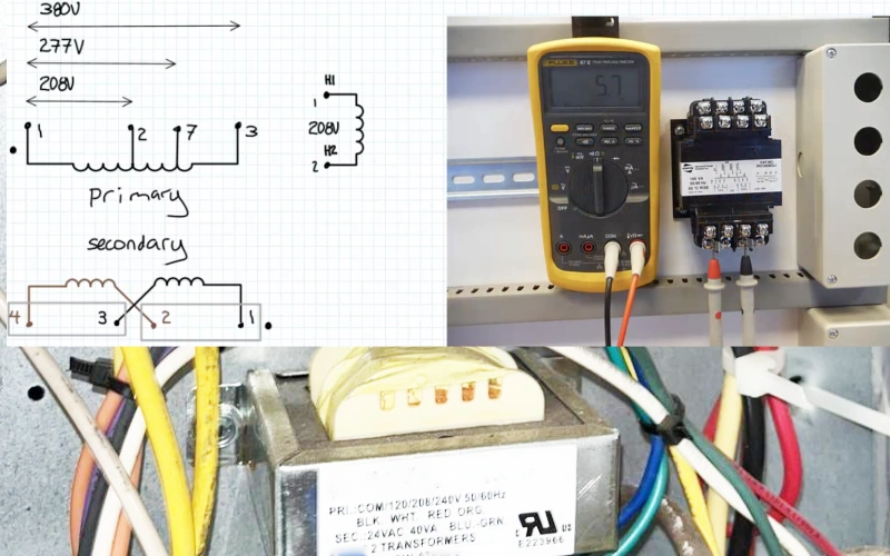
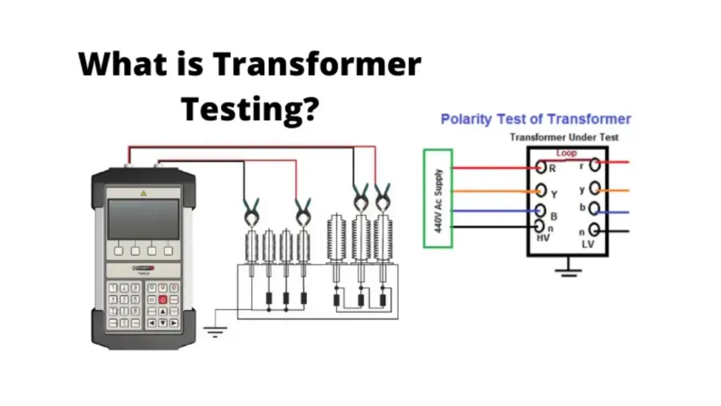
Turns Ratio Test
The turns ratio test verifies the relationship between the number of turns in the primary winding and the number of turns in the secondary winding. This1 test ensures that the transformer will provide the correct output voltage for a given input voltage. An incorrect turns ratio can indicate problems such as shorted turns or winding faults. The test is usually conducted by applying a low-voltage AC signal to one winding and measuring the voltage across the other winding.
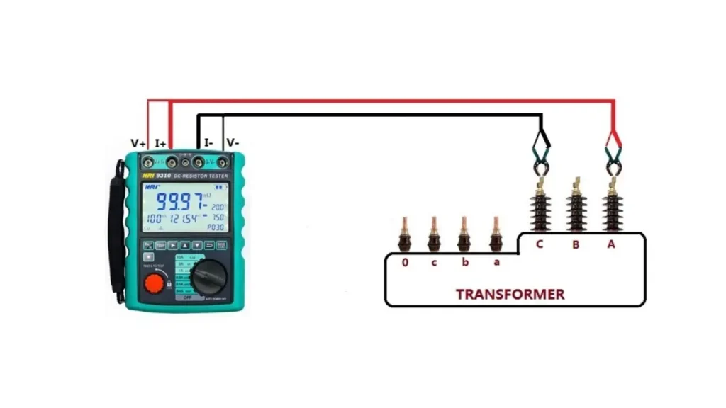
Winding Resistance Test
The winding resistance test measures the DC resistance of the transformer windings. This test helps to identify any imbalances in the windings, loose connections, broken strands, or high-resistance joints. Abnormally high resistance can lead to increased losses and overheating. The test is performed by applying a DC current to the winding and measuring the voltage drop across it.
Impedance Test (Short-Circuit Test)
The impedance test, also known as the short-circuit test, determines the transformer’s impedance, which is its opposition to the flow of alternating current. This test is performed by short-circuiting one winding and applying a reduced voltage to the other winding until rated current flows. The results of this test are used to calculate the transformer’s impedance voltage and losses, which are important for determining its performance and ability to withstand short-circuit conditions.
Induced Voltage Test
The induced voltage test is a high-voltage test that assesses the integrity of the transformer’s insulation between turns and layers of the windings. It involves applying a higher-than-normal voltage at a higher frequency to one winding, while the other winding is open-circuited. This test stresses the insulation and helps to detect any weaknesses or potential for failure under overvoltage conditions.
Applied Voltage Test
The applied voltage test, also known as the dielectric withstand test, checks the ability of the transformer’s insulation to withstand high voltages between the windings and ground. A high voltage is applied between the windings and the transformer’s core and enclosure for a specific duration. This test ensures that the insulation can withstand transient overvoltages and provides a measure of the transformer’s overall insulation strength.
Dry Type Transformer Insulation Resistance Testing
Insulation resistance testing of dry-type transformers is a critical procedure to assess the health and integrity of the transformer’s insulation system. This test, typically performed using a megohmmeter (megger), measures the resistance between the windings and ground, as well as between the different windings.
High insulation resistance values indicate that the insulation is in good condition and effectively preventing current leakage, while low values can signal degradation due to factors like moisture ingress, contamination from dust or chemicals, or thermal aging of the insulation materials. Regular insulation resistance testing helps in identifying potential insulation failures before they lead to significant operational issues or safety hazards.
During the test, the transformer is de-energized and isolated from the electrical system. The megger applies a DC voltage (typically ranging from 500V to 5kV, depending on the transformer’s voltage rating) and measures the resulting current flow. According to Ohm’s law, a high resistance will result in a very low current.
The measured resistance value, usually expressed in megohms (MΩ), is then compared to previous test results and industry standards or manufacturer recommendations to determine the condition of the insulation. Tracking these values over time can provide valuable insights into the rate of insulation degradation and aid in predictive maintenance planning.
Here are key aspects of dry-type transformer insulation resistance testing:
- Test Connections: Measurements are typically taken between each winding and ground, and between each pair of windings (e.g., high voltage to ground, low voltage to ground, high voltage to low voltage).
- Test Voltage: The applied DC test voltage is selected based on the transformer’s voltage rating, as per relevant standards (e.g., IEEE, IEC).
- Duration of Test: Readings are usually taken after a specific period of time, such as 1 minute, to allow for stabilization of the current. Some advanced tests may involve taking readings at multiple time intervals (e.g., 15 seconds, 60 seconds, 10 minutes) to calculate Polarization Index (PI) and Dielectric Absorption Ratio (DAR), providing further insights into the insulation condition.
- Temperature Correction: Insulation resistance is temperature-dependent. It’s important to record the ambient temperature during testing and apply correction factors if comparing readings taken at different temperatures.
- Acceptance Criteria: Minimum acceptable insulation resistance values are often specified in industry standards or by the transformer manufacturer, based on the transformer’s voltage rating and age.
Dry Type Transformer Megger Test
The megger test, or insulation resistance test, is a fundamental diagnostic procedure for dry-type transformers, assessing the health of their insulation system. By applying a DC voltage, typically ranging from 500V to 5kV, the megger measures the resistance to current flow between the windings and ground, as well as between the windings themselves.
High resistance values indicate good insulation integrity, effectively preventing leakage currents, while low readings suggest potential insulation degradation due to moisture, contamination, or thermal aging, warranting further investigation. Tracking these measurements over time is crucial for proactive maintenance and preventing unexpected failures.
Here are key aspects of a dry-type transformer megger test:
- Purpose: To evaluate the condition of the transformer’s insulation.
- Instrument: A megohmmeter (megger) is used to apply a DC voltage and measure resistance.
- Connections: Tests are performed between each winding and ground, and between primary and secondary windings.
- Voltage Application: The test voltage is selected based on the transformer’s voltage rating.
- Reading Interpretation: High resistance (in megaohms) generally indicates good insulation; low resistance suggests potential problems.
- Temperature Correction: Readings should be corrected for temperature for accurate comparison over time.
Dry Type Transformer Testing and Commissioning
The megger test, or insulation resistance test, is a fundamental diagnostic procedure for dry-type transformers, assessing the health of their insulation system. By applying a DC voltage, typically ranging from 500V to 5kV, the megger measures the resistance to current flow between the windings and ground, as well as between the windings themselves.
High resistance values indicate good insulation integrity, effectively preventing leakage currents, while low readings suggest potential insulation degradation due to moisture, contamination, or thermal aging, warranting further investigation. Tracking these measurements over time is crucial for proactive maintenance and preventing unexpected failures.
Here are key aspects of a dry-type transformer megger test:
- Purpose: To evaluate the condition of the transformer’s insulation.
- Instrument: A megohmmeter (megger) is used to apply a DC voltage and measure resistance.
- Connections: Tests are performed between each winding and ground, and between primary and secondary windings.
- Voltage Application: The test voltage is selected based on the transformer’s voltage rating.
- Reading Interpretation: High resistance (in megaohms) generally indicates good insulation; low resistance suggests potential problems.
- Temperature Correction: Readings should be corrected for temperature for accurate comparison over time.
Power Factor Testing Dry Type Transformers
Power factor testing on dry-type transformers is a diagnostic method used to evaluate the condition of the insulation system by measuring the dielectric losses. It determines the power factor, which is the ratio of the energy dissipated as heat in the insulation to the total energy applied.
A low power factor indicates good, healthy insulation with minimal losses, while a high power factor suggests insulation degradation due to factors like moisture, contamination, or aging. This test is typically performed using specialized power factor test sets that apply an AC voltage and measure the resulting current and phase angle.
Here are key aspects of power factor testing for dry-type transformers:
- Purpose: To assess the overall condition of the insulation system and detect deterioration.
- Measurement: It measures the dielectric losses within the insulation materials.
- Instrumentation: A power factor test set (often a Doble test set or similar) is used to apply AC voltage and measure current and phase angle.
- Interpretation: Higher power factor values indicate increased losses and potential insulation problems.
- Trending: Regular power factor testing allows for tracking changes in insulation condition over time.
- Voltage Dependence: Some power factor tests, like the tip-up test, involve measurements at different voltage levels to detect voltage-dependent issues like partial discharge.
Conclusion
In essence, both factory and field testing play vital, yet distinct, roles in ensuring the integrity and reliable operation of dry-type transformers. Factory tests provide a controlled environment for comprehensive initial assessments, while field tests verify performance under actual operating conditions and during maintenance.
Understanding the differences between these testing phases allows for a holistic approach to transformer management, maximizing uptime and preventing potential failures. By adhering to recommended testing schedules and interpreting results accurately, you can safeguard your electrical infrastructure.
For a comprehensive range of high-quality dry-type transformers and expert support, Linkwell Electrics is your trusted partner, providing solutions tailored to your specific testing and application needs.