Connecting a cabinet thermostat correctly is crucial for ensuring optimal temperature control and protecting sensitive equipment within industrial enclosures. This process, while straightforward, requires attention to detail and adherence to safety guidelines. Improper wiring can lead to system malfunctions, energy waste, or even damage to your valuable components.
This blog post will guide you through the essential steps for wiring your cabinet thermostat, making the process clear and manageable. We’ll cover key considerations from safety precautions to proper terminal connections, empowering you to achieve efficient thermal management for your project.
What is a Cabinet Thermostat?
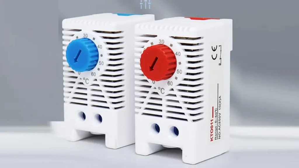
A cabinet thermostat is a specialized temperature control device designed to monitor and regulate the internal climate of electrical and electronic enclosures, also known as cabinets or control panels.
Its primary function is to maintain an optimal operating temperature range for sensitive components housed within, preventing issues like overheating, which can lead to equipment failure, and condensation, which can cause short circuits and corrosion.
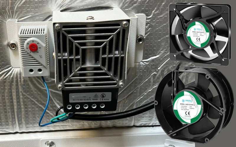
These compact devices typically activate cooling elements (like fans) when the temperature rises too high, or heating elements (like anti-condensation heaters) when it drops too low, ensuring the longevity and reliable performance of the enclosed machinery.
How to Connect a Cabinet Thermostat?
This guide delves into the specifics of connecting cabinet thermostats, providing a comprehensive understanding of both Normally Closed (NC) and Normally Open (NO) configurations. Proper wiring is fundamental for effective thermal regulation and protecting sensitive equipment within your enclosures.
1. Understanding NC (Normally Closed) Thermostats
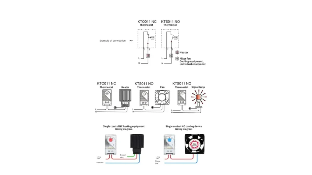
Cabinet thermostats are specifically engineered for controlling heating elements within an enclosure. Their “normally closed” designation means that, at temperatures below their set point, their internal electrical contacts remain closed, completing the circuit and allowing power to flow to the connected heater. As the enclosure temperature rises and surpasses the set threshold, the thermostat’s bimetallic strip or sensor expands, causing the contacts to open and interrupt the power to the heater, thus preventing overheating.
For wiring, the main power supply’s live (L) and neutral (N) conductors are connected directly to the corresponding input terminals on the cabinet thermostat. The heater’s power input is then connected in series with the thermostat’s output terminals.
This configuration ensures that the thermostat acts as a critical switch, controlling the heater’s operation based on the detected internal temperature. A separate ground wire connection to the heater and the enclosure is also essential for safety, protecting against electrical faults.
2. Understanding NO (Normally Open) Thermostats
Conversely, KTS011 NO thermostats are designed for cooling applications, such as activating filter fans or cooling units. Their “normally open” characteristic means that, at temperatures below their set point, their internal contacts remain open, breaking the circuit and preventing power from reaching the cooling device.
When the enclosure temperature rises above the preset limit, the thermostat’s sensor causes the contacts to close, thereby completing the circuit and supplying power to the cooling equipment, which then works to reduce the internal temperature.
Regarding connections, the live (L) and neutral (N) power supply lines are wired to the input terminals of the KTS011 thermostat. The filter fan or cooling equipment’s power input is then connected in series with the thermostat’s output terminals.
This setup allows the thermostat to effectively switch the cooling device on only when the enclosure reaches an elevated temperature, preventing unnecessary operation. As with heating setups, proper grounding of the cooling device and enclosure is critical for safe electrical practices.
3. Wiring for Different Devices
The provided diagrams comprehensively illustrate diverse connection scenarios for both NC and NO thermostats. For NC thermostats, the “Single control NC heating equipment Wiring diagram” clearly depicts the series connection of the KTO011 thermostat with a heater, showing the flow of live (L) and neutral (N) lines, along with the crucial ground wire. This ensures the heater activates precisely when cooling is required.
Similarly, for NO thermostats, the “Single control NO cooling device Wiring diagram” demonstrates the series connection of the KTS011 thermostat with a cooling fan. This visual aid clarifies how the fan receives power only when the thermostat’s contacts close due to high temperatures. Additionally, the cabinet thermostat” example with a “Signal lamp” illustrates how the thermostat can also be used to trigger an alarm or indicator light when a specific temperature condition is met, offering versatile monitoring capabilities beyond just heating or cooling.
4. Essential Safety Precautions
Before commencing any wiring, always ensure the main power supply to the enclosure is completely disconnected and locked out. Use a reliable voltage tester to confirm that no power is present at any of the connection points. This critical step prevents electrical shock and damage to both the installer and the equipment.
Always adhere to local electrical codes and standards. Ensure all wiring is appropriately sized for the current load and properly insulated. Using ferrules or crimp connectors for terminal connections is highly recommended to ensure secure and reliable electrical contact, preventing loose connections that can lead to arcing or equipment malfunction.
5. Post-Installation Testing and Adjustment
Once all connections are securely made, meticulously double-check every wire against the specific wiring diagram to confirm correct placement and polarity. After verifying all connections, carefully restore power to the enclosure. Monitor the thermostat and the connected heating or cooling device to ensure they activate and deactivate as expected according to the set temperature thresholds.
Adjust the thermostat’s set point as necessary to achieve the desired internal enclosure temperature. It is advisable to allow the system to run for a period to stabilize and then fine-tune the settings for optimal thermal management. Regular checks of the connections and functionality are recommended for long-term reliable operation.
Where to Install Cabinet Thermostats
Cabinet thermostats are essential components for managing the internal environment of various enclosures, playing a critical role in protecting sensitive equipment from temperature fluctuations. Their installation is crucial in environments where maintaining a stable temperature is vital for operational reliability and equipment longevity.
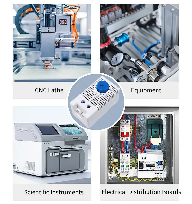
You’ll find cabinet thermostats predominantly in:
- Industrial Control Panels: Protecting PLCs, motor drives, and other automation components from overheating or freezing.
- Electrical Distribution Boards: Ensuring the stable operation of circuit breakers, contactors, and wiring by preventing excessive heat buildup.
- Outdoor Enclosures: Safeguarding telecommunications equipment, signal boxes, and other outdoor electronics from harsh weather conditions and condensation.
- CNC Machine Tools: Providing precise temperature control for sensitive electronic components within the machine’s control cabinet, crucial for accuracy and performance.
- Scientific Instruments: Maintaining consistent internal temperatures for laboratory equipment and analytical devices to ensure accurate and reliable results.
Conclusion
Connecting a cabinet thermostat is a crucial step in safeguarding your valuable equipment. While the specifics depend on the thermostat model and your existing setup, the core process involves ensuring power is safely off, carefully identifying and labeling existing wires, and then correctly connecting them to the new thermostat’s terminals. This ensures proper communication for heating or cooling functions.
Always prioritize safety by disconnecting power at the source and verifying with a voltage tester before handling any wires. Referencing the thermostat’s specific wiring diagram and instructions is paramount for a successful installation, as color codes and terminal designations can vary. When in doubt, consulting a qualified electrician can prevent damage and ensure optimal performance.
For your next project, consider sourcing your wholesale cabinet thermostats from us. We offer a diverse range of reliable, energy-efficient, and customizable solutions designed to meet stringent industrial demands. Contact us today to discuss your requirements and discover how our high-quality thermostats can provide superior thermal management for your enclosures.