If you want to know how to check a relay step by step, you first need to focus on safety and use the right tools. You’ll often find relays inside Linkwell electrical control panels and accessories, so knowing how to check a relay helps keep your equipment reliable. Before you test, always disconnect power.
Many safety incidents happen during relay testing, like chattering, false switching, or unwanted triggering of safety systems. Use a multimeter and follow each test carefully. Taking these steps makes sure your relay and your panel work as they should.
Relay Key Takeaways
- Always disconnect power before testing a relay to stay safe and protect your equipment.
- Use the right tools like a multimeter, relay tester, and insulated gloves for accurate and safe testing.
- Identify the relay and its pin layout carefully to avoid mistakes and damage during testing.
- Test the relay by checking coil resistance, listening for a click when energized, and verifying contact continuity.
- Replace relays that show faulty readings, no click, or visible damage to keep your system reliable and safe.
Check a Relay Safety and Preparation
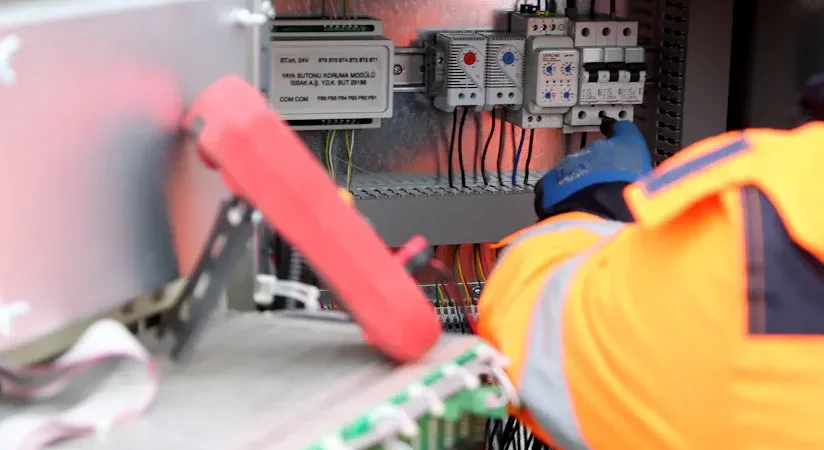
Disconnect Power
Before you do anything else, always disconnect the power to your electrical control panel. This step keeps you safe and protects your equipment from damage. Many accidents happen because people skip this part or rush through it. You don’t want to risk electric shock or cause a short circuit. Make sure you double-check that all power sources are off before you start any relay test. If your panel has a lockout/tagout system, use it. This simple habit can save you from serious injury.
Tip: Never assume a panel is safe just because a switch is off. Use a voltage tester to confirm there’s no live current.
Safety standards matter, too. Different countries and regions have their own rules for electrical safety. Here’s a quick look at some of the main standards you might see:
| Region / Country | Relevant Safety Standards | Focus of Safety Requirements | Certification Bodies / Marks |
|---|---|---|---|
| North America (USA, Canada) | UL (USA), CSA (Canada) | Fire prevention, temperature rise | UL, CSA |
| Europe | EN/IEC Standards | Electric shock prevention | VDE, TUV-Rh |
| International | IEC Standards | Technical electric standards | N/A |
| Germany | VDE Standards | National safety standards | N/A |
| UK | BSI Standards | National safety standards | N/A |
| China | GB Standards | Fire and shock prevention | CCC |
| Japan | JIS Standards | National safety standards | N/A |
Following these standards helps you avoid common mistakes, like overlooking safety protocols or using outdated materials. Always stay updated and follow the latest guidelines.
Gather Tools
You need the right tools to safely and accurately test a relay. Start with a multimeter. This tool checks coil resistance and verifies if the relay is working. A relay tester is also helpful because it applies voltage and checks continuity, making the process faster. For insulation checks, a megger comes in handy. Don’t forget insulated gloves—they protect your hands from accidental shocks. Before you begin, do a quick visual inspection for any obvious damage or loose wires.
Here’s a handy checklist for your relay test setup:
- Multimeter
- Relay tester
- Megger (for insulation resistance)
- Insulated gloves
- Voltage tester
- Screwdrivers and basic hand tools
Linkwell’s electrical control panels and accessories are designed with safety in mind. Their clear labeling and modular layouts make it easier for you to access relays and perform each test without confusion. Remember, skipping hands-on practice or ignoring feedback can lead to mistakes. Take your time, use the right tools, and always put safety first.
Identify and Access the Relay
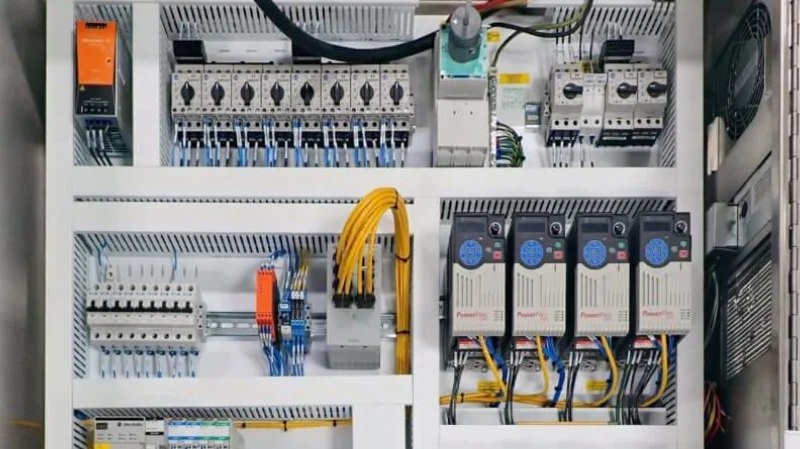
Locate in Control Panel
You’ll usually find relays inside your electrical control panel, often grouped with other control components. If you’re working with a Linkwell panel, you’re in luck. Linkwell designs its panels with clear labeling and a modular layout, so you can spot relays quickly. Look for a rectangular or square component with several pins or screw terminals. Relays might sit near contactors, circuit breakers, or terminal blocks. Take a moment to check the panel’s wiring diagram or the label on the inside of the door. This diagram shows you exactly where each relay sits and what it controls.
Tip: Good lighting makes a big difference. Use a flashlight or the panel’s built-in lighting to help you see small labels and pin numbers.
If you’re not sure which part is the relay, look for markings like “K1” or “Relay” on the panel or next to the component. Linkwell’s panels often use these clear labels to help you avoid confusion. Once you spot the relay, make sure you have enough space to work. If needed, remove any covers or barriers, but always keep safety in mind.
Note Pin Configuration
Before you start testing, take a close look at the relay’s pin configuration. Each relay has a unique layout for its coil and contacts. You’ll usually see a diagram printed on the relay itself or in the panel’s documentation. This diagram tells you which pins connect to the coil, which are common, and which are normally open (NO) or normally closed (NC).
Understanding the pin configuration is essential for accurate and safe relay testing. When you know which pins do what, you can connect your multimeter or test leads correctly. This helps you avoid mistakes like applying voltage to the wrong pins or damaging sensitive parts inside the relay. If you mix up the pins, you might get false test results, damage the relay, or even create a safety hazard.
- Plugging a relay into the wrong socket or misidentifying pins can cause unpredictable and damaging outcomes.
- Incorrect pin identification can lead to electrical shorts, sparks, or even component failure.
- Testing with the wrong pin assignments risks damaging the relay or the control circuit.
- Always use the correct pin diagram and double-check before you connect anything.
Take your time with this step. Use the panel’s wiring diagram, the relay’s datasheet, or a multimeter to confirm each pin’s function. Linkwell’s modular design and clear labeling make this process much easier, helping you avoid costly mistakes and keeping your testing safe.
How to Check a Relay
When you want to know how to check a relay, you need a clear process. Let’s break it down into three main steps: testing coil resistance, energizing the relay, and checking contact continuity. These steps work for both testing coil relays and testing solid-state relays. You’ll use a multimeter for most of these tests, and Linkwell’s screw terminals and push button switches make your setup safer and more reliable.
Test Coil Resistance
Start with the coil. This is the heart of the relay. If the coil is faulty, the relay won’t work at all. Here’s how to test a relay coil using a multimeter:
- Set your multimeter to the resistance (Ω) mode. Choose a range that matches the expected coil resistance.
- Find the two coil pins on the relay. You can check the relay’s diagram or the panel’s wiring chart.
- Touch the multimeter probes to the coil pins. Polarity doesn’t matter for this test.
- Read the resistance value on the display.
Now, compare your reading to the standard values. Here’s a quick reference table for common coil resistances:
| Coil Type | Rated Voltage (V) | Approximate Coil Resistance Range (Ω) |
|---|---|---|
| AC | 6 | ~4 to 6.3 |
| AC | 12 | ~4.7 |
| AC | 24 | ~19 |
| AC | 50 | ~82 |
| AC | 100/110 | ~340 |
| AC | 200/220 | ~620 to 1540 |
| DC | 6 | ~2.1 to 2.7 |
| DC | 12 | ~68 |
| DC | 24 | ~275 |
| DC | 48 | ~1,180 |
| DC | 100/110 | ~5,750 |
| DC | 125 | ~7,430 |
| DC | 200/220 | ~18,000 to 23,200 |
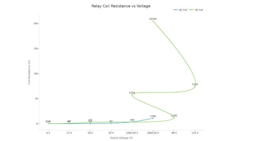
If your reading matches the expected value, your coil is healthy. If you see a very low value, the coil might be shorted. A very high or infinite reading means the coil is open or broken. This is a key part of how to check a relay, and it works for both testing coil relays and testing solid-state relays.
Tip: Linkwell screw terminals help you connect your multimeter probes securely, so you get accurate readings without loose wires.
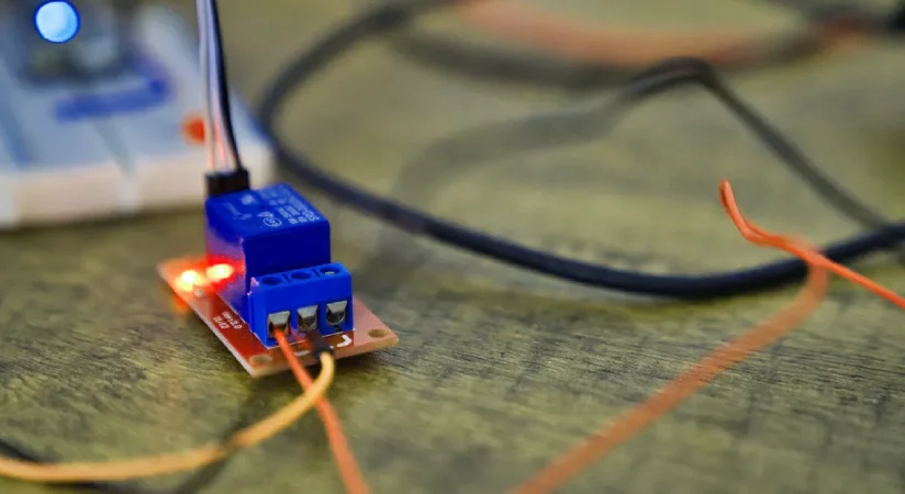
Energize and Listen for Click
Next, you want to see if the relay actually works when powered. Here’s how to test a relay by energizing the coil:
- Apply the rated voltage to the coil pins. You can use a power supply or a battery that matches the relay’s voltage.
- Listen closely. A working relay makes a clear “click” sound when it switches. This click means the internal contacts have moved.
- If you don’t hear a click, the relay might be faulty or the coil is not getting power.
You can also feel a slight movement if you touch the relay gently. This step is important in how to check a relay because it confirms the coil is strong enough to move the contacts.
Note: Linkwell push button switches let you control when to energize the relay, so you avoid accidental switching and keep your test safe.
Check Contact Continuity
The last step is to check if the relay’s contacts are opening and closing as they should. Here’s how to test a relay’s contacts:
- Set your multimeter to continuity mode (look for the symbol that looks like a sound wave).
- Find the common (COM), normally closed (NC), and normally open (NO) pins on the relay.
- With the relay de-energized, place one probe on COM and the other on NC. You should hear a beep or see continuity. There should be no continuity between COM and NO.
- Energize the relay again. Now, test between COM and NO. You should hear a beep or see continuity. There should be no continuity between COM and NC.
- If you hear the beep in the right places, your relay is working.
- If you hear beeps in both states, the contacts might be stuck or welded.
- If you never hear a beep, the contacts could be broken or open.
Alert: Always use insulated tools and double-check your connections. Linkwell screw terminals keep your test leads secure and organized, reducing the risk of accidental shorts.
Knowing how to check a relay with these steps helps you spot problems early. You can use this method for both testing coil relays and testing solid-state relays. If you follow these steps, you’ll get reliable results every time you test a relay.
How to Test a Relay in Linkwell Panels
Use Fan Filter Unit for Safe Testing
When you test a relay inside a Linkwell control panel, you want the environment to be as stable as possible. That’s where the fan filter unit comes in. This small but powerful device keeps your panel cool and clean, which helps you get accurate results every time you test a relay.
Here’s how the fan filter unit makes your job safer and easier:
- It provides steady cooling, so heat never builds up around sensitive parts like relays.
- The filter blocks dust, moisture, and other particles, which means less risk of corrosion or short circuits.
- Continuous airflow keeps the temperature and humidity even, even if your panel sits in a tough spot.
- The unit uses industrial-grade parts and strong filters, so you can count on it for years.
- You can add a thermostat to control the fan automatically, saving energy and protecting your equipment.
- Maintenance is simple. You can swap out filters quickly, keeping the system running at its best.
With these features, you don’t have to worry about sudden temperature spikes or dust sneaking in while you test a relay. You get a safer, more reliable workspace.
Verify with Enclosure Heater
Sometimes, you need to test a relay in cold or damp conditions. Linkwell’s enclosure heater steps in to keep things dry and warm. This heater has a tough IP65 or IP66 rating, so it blocks dust and water from getting inside your panel.
Here’s what the enclosure heater does for you:
- It keeps the inside of your panel dry, stopping condensation and moisture from causing problems.
- Stable temperatures mean your relay tests stay accurate, even if the weather outside changes.
- The heater protects against corrosion and electrical failures, so your sensitive electronics last longer.
Tip: Always check that your enclosure heater works before you start testing. A dry, warm panel gives you the best chance for a successful test.
Why Environment Matters
Environmental factors inside your control panel can change your test results. Take a look at this table to see how different conditions affect your relay testing:
| Environmental Factor | Impact on Relay Testing Outcomes |
|---|---|
| Temperature Stability | Unstable temperatures can cause unreliable or inconsistent results. |
| Humidity Control | High or low humidity affects test accuracy and can damage components. |
| Air Circulation | Poor airflow creates hot or cold spots, leading to inconsistent results. |
| Insulation & Sealing | Leaks let in outside air, making it hard to control temperature and humidity. |
Easy Access with Modular Panel Design
Linkwell’s modular panel design makes it simple to reach and test a relay. You can add or remove components without rewiring. The DIN rail system keeps everything organized and secure. Labels help you find the right relay fast. You can disconnect circuits safely and even use built-in test sockets for quick checks. This setup saves you time and keeps your testing process smooth.
Troubleshooting and Results
Interpret Test Results
When you test a relay, your multimeter readings and what you hear or see tell you a lot. If you measure coil resistance between the coil pins (often labeled 85 and 86), you should see a value between 50 and 120 ohms—usually close to 75 ohms. If your meter shows “OL” or a very high number, the coil is open and the relay is faulty. A very low value means the coil is shorted.
Check the contacts next. With the relay de-energized, the Normally Open (NO) contacts should show infinite resistance, while the Normally Closed (NC) contacts should show near zero. When you energize the relay, the NO contacts should drop to near zero, and the NC contacts should go to infinite resistance. You should also hear a clear click when you power the coil. No click means the relay isn’t switching.
Here’s a quick reference table:
| Test Type | Healthy Reading | Faulty Relay Indication |
|---|---|---|
| Coil Resistance | 50–120 Ω (typically ~75 Ω) | “OL” or very high/low value |
| NO Contacts (De-energized) | Infinite resistance | Any continuity (stuck contacts) |
| NO Contacts (Energized) | Near 0 Ω (continuity) | No continuity (open circuit) |
| NC Contacts (De-energized) | Near 0 Ω (continuity) | Open circuit (infinite resistance) |
| NC Contacts (Energized) | Infinite resistance | Continuity (stuck contacts) |
| Audible Click | Yes | No click |
If your readings don’t match these, you may have found the symptoms of a bad relay.
When to Replace
You should replace a relay if you see any of these signs:
- The coil shows “OL” or a value far from the expected range.
- The contacts do not switch states when energized.
- You hear no click when you apply voltage.
- The relay gets hot or shows visible damage.
If you’re working in a Linkwell panel, always turn off the main power and double-check with a tester. Inspect all wiring and connections for loose or broken wires. Fix any issues, then retest. If the relay still fails, it’s time to swap it out.
Tip: Always use a replacement relay with the exact same part number and ratings. This keeps your system safe and prevents new problems.
Test a Relay by Swapping
Sometimes, the fastest way to test a relay is to swap it with a known good one. Remove the suspect relay and insert a matching relay from a non-critical spot in your panel. If the problem goes away, you’ve confirmed the relay was bad. If the issue remains, you may need to look elsewhere in your system.
- Swapping works best when you use a relay that matches exactly in part number and ratings.
- Never use a relay that only looks similar—differences in ratings can cause damage.
- If swapping doesn’t solve the problem, check your wiring, connections, and other components.
This method is quick and reliable, especially in modular Linkwell panels where relays are easy to access and replace.
You now know how to check a relay step by step. Always start with safety, gather your tools, and follow a clear process. Here’s a quick checklist to guide your next test:
- Define your relay’s function and set clear goals.
- Use the right equipment and calibrate before each test.
- Follow detailed procedures and document every result.
- Analyze your findings and act fast if you spot issues.
- Train yourself on modern test methods for better results.
Using high-quality components from Linkwell keeps your electrical control panels reliable and safe. Regular relay testing helps you avoid costly downtime and keeps your system running smoothly. If you ever feel unsure or your test results seem off, reach out to a professional. Routine testing, along with the right tools and training, makes all the difference in keeping your equipment efficient and safe.
FAQ
How often should you check relays in your control panel?
You should check relays every six months. Regular checks help you catch problems early. If you notice any strange noises or your equipment acts up, test the relay right away.
Can you use these steps for automotive relays?
Yes, you can use these steps for automotive relays. The process is almost the same. Just make sure you follow your vehicle’s safety guidelines and use the right voltage for testing.
What if your relay passes the test but equipment still fails?
If your relay tests fine but your equipment still does not work, check the wiring and other components. Sometimes, the problem comes from a loose wire or a faulty switch, not the relay itself.
Do you need special tools to test a relay?
You do not need fancy tools. A basic multimeter, insulated gloves, and a voltage tester work for most relay tests. For more advanced checks, you might use a relay tester or a megger.
Is it safe to swap relays between different circuits?
You should only swap relays if they have the same part number and ratings. Using the wrong relay can damage your equipment or cause safety issues. Always double-check before swapping.
Conclusion
Knowing how to check a relay step by step keeps your electrical control panel safe and reliable. By following a tested process—disconnecting power, inspecting coil resistance, and verifying contact continuity—you prevent failures before they happen. Linkwell’s smart panel designs, modular layouts, and reliable components make testing easier and more accurate. Regular relay checks help reduce downtime, avoid costly damage, and ensure long-lasting equipment performance in any industrial setup.