Testing a control transformer is essential to ensure its proper functionality, safety, and ability to reliably power control circuits. Regular testing can identify potential issues like winding shorts, open circuits, or incorrect voltage output before they lead to system failures or safety hazards. This proactive approach helps maintain operational efficiency and prevents costly downtime in industrial and commercial applications.
This blog post will guide you through the fundamental steps involved in testing a control transformer. We will cover essential procedures and safety precautions to help you assess the transformer’s condition and verify its performance characteristics, ensuring it meets the required specifications for your control system.
What are Control Transformers
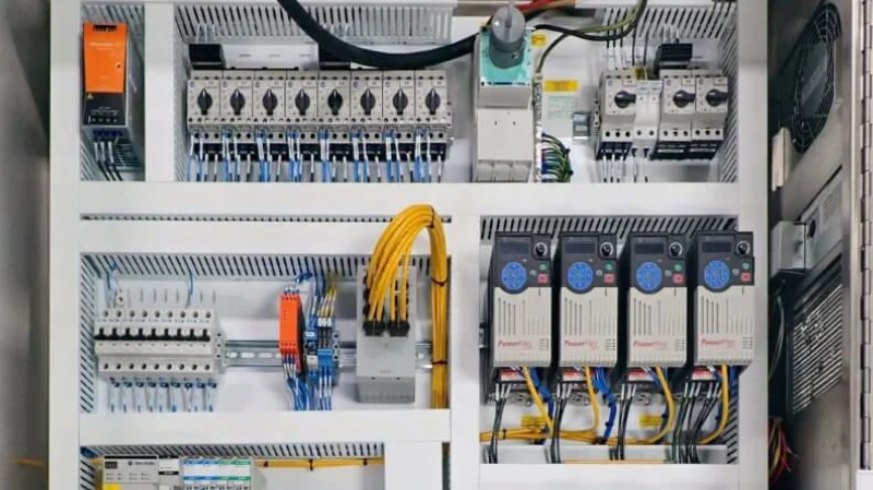
Control transformers are specialized isolation transformers designed to provide a stable and reduced voltage to control circuits, typically found in industrial and commercial applications across the United States.
They step down higher voltages (like 240V or 480V) to lower, safer voltages (often 24V or 120V) needed to power relays, contactors, timers, and other control components, ensuring the reliable and safe operation of machinery and automated systems.
What to Test for Control Transformer
When testing a control transformer, focus on verifying its basic functionality and safety. Key aspects to check include the continuity of both primary and secondary windings, ensuring there are no breaks in the coils. It’s also crucial to test the output voltage under no load to confirm it matches the transformer’s rating when the correct input voltage is applied. Additionally, check for short circuits between the primary and secondary windings and between the windings and the transformer’s core. Finally, assessing the insulation resistance can reveal potential degradation that might lead to future failures.
Here’s a summary of what to test:
- Continuity of primary winding
- Continuity of secondary winding
- Output voltage under no load
- Short circuits between windings
- Short circuits to the core
- Insulation resistance (advanced)
How to Test a Control Transformer?
Testing a control transformer is essential to verify its functionality, ensure it’s providing the correct output voltage, and confirm its overall health and safety. A series of basic tests can be performed using common electrical testing equipment. These tests help identify potential issues such as open windings, short circuits, and insulation breakdown, ensuring the reliable operation of your control system.
Here is the guide about how to test a transformer with a multimeter?
Tools Needed:
- Multimeter (capable of measuring AC/DC voltage and resistance)
- Screwdrivers (appropriate for the transformer terminal screws)
- Safety glasses
Step 1: Visual Inspection and Continuity Check
Begin by performing a thorough visual inspection of the control transformer. Look for any signs of physical damage such as cracks in the casing, bulging or leaking, burnt insulation, or loose connections. Ensure that the terminal blocks are intact and that there are no loose wires. A careful visual check can often reveal obvious problems before any electrical testing is performed.
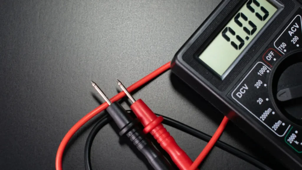
Next, use a multimeter to perform a continuity check on both the primary and secondary windings. With the transformer disconnected from the power source, set your multimeter to the resistance (Ω) setting. Place the probes across the terminals of each winding. You should get a low resistance reading, indicating continuity. An open circuit (infinite resistance) suggests a broken winding, while a very low resistance reading might indicate a short circuit within the winding.
Step 2: Primary Voltage Test
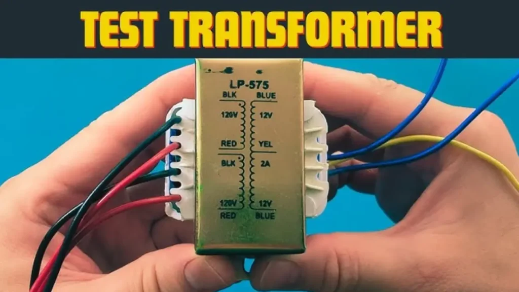
This step involves applying the rated primary voltage to the transformer and measuring the input voltage. Ensure all safety precautions are taken when working with live circuits. Connect the primary winding of the control transformer to the appropriate voltage source as indicated on the transformer’s nameplate. Use your multimeter, set to AC voltage, to measure the voltage across the primary terminals while the power is applied.
The measured primary voltage should be close to the rated input voltage of the transformer. A significant deviation could indicate an issue with the power supply or incorrect wiring. If the primary voltage is correct, proceed to the secondary voltage test. If there is no voltage reading, double-check your connections and the power source.
Step 3: Secondary Voltage Test
The secondary voltage test verifies that the transformer is stepping down the voltage correctly according to its turns ratio. With the primary voltage applied (as in Step 2), use your multimeter, still set to AC voltage, to measure the voltage across the secondary terminals. The measured secondary voltage should be close to the rated output voltage specified on the transformer’s nameplate.
A significantly higher or lower secondary voltage than expected indicates a potential problem with the transformer, such as incorrect turns ratio or internal faults. A reading of zero voltage suggests an open circuit in the secondary winding or a major internal failure. Compare your measured values with the nameplate ratings to determine if the transformer is functioning as expected.
Step 4: Insulation Resistance Test (Megger Test – Advanced)
For a more comprehensive assessment of the transformer’s health, an insulation resistance test, often called a megger test, can be performed. This test measures the resistance of the insulation between the windings and between the windings and the core. A megohmmeter (megger) is used to apply a high DC voltage (typically 500V or 1000V) and measure the leakage current.
A high insulation resistance reading (typically in the megaohms or gigaohms range) indicates good insulation. Low insulation resistance suggests degradation of the insulation, which could lead to short circuits and transformer failure. This test should be performed with the transformer disconnected from all circuits and is particularly useful for identifying potential insulation breakdown due to age, moisture, or contamination.
How to Test a Transformer With an Ohmmeter?
Testing a transformer with an ohmmeter is a fundamental way to check the continuity of its windings and identify potential short circuits or open circuits. This method is performed with the transformer completely disconnected from any power source to ensure safety and accurate readings. By measuring the resistance across the primary and secondary windings, you can gain valuable insights into the basic electrical integrity of the transformer.
Tools Needed:
- Multimeter (with resistance measurement capability – ohmmeter)
- Safety glasses
Step 1: Disconnect the Transformer and Set Up the Ohmmeter
Before commencing any testing, ensure the transformer is completely disconnected from any power source or external circuits. This is a crucial safety precaution to prevent electrical shock and to obtain accurate resistance measurements. Verify that no wires are connected to the primary or secondary terminals.
Next, set your multimeter to the resistance (Ω) measurement mode. Choose a low resistance range initially, as transformer windings typically have low resistance values. Some multimeters have an auto-ranging feature, which can simplify this step. Ensure the multimeter probes are clean and in good condition for accurate readings.
Step 2: Test the Primary Winding Resistance
Place the multimeter probes across the terminals of the primary winding. Observe the resistance reading displayed on the multimeter. A low but finite resistance value indicates that the primary winding is likely intact and has continuity. The exact value will depend on the transformer’s specifications, but it should not be zero (indicating a short circuit) or infinite (indicating an open circuit).
Record the resistance reading for the primary winding. This value can be useful for comparison with the secondary winding or with readings from a known good transformer of the same type. An unexpected high or low resistance reading can be a sign of a problem within the primary winding.
Step 3: Test the Secondary Winding Resistance
Similarly, place the multimeter probes across the terminals of the secondary winding. Observe and record the resistance reading. Like the primary winding, the secondary winding should exhibit a low but finite resistance value, indicating continuity. The specific resistance will depend on the secondary voltage and current rating of the transformer.
Compare the resistance reading of the secondary winding to that of the primary winding. For step-down transformers (common for control applications), the primary winding often has a higher resistance than the secondary winding due to having more turns of thinner wire. Again, a reading of zero or infinity suggests a fault within the secondary winding.
Step 4: Check for Short Circuits Between Windings and to the Core
To check for short circuits between the primary and secondary windings, place one multimeter probe on a terminal of the primary winding and the other probe on a terminal of the secondary winding. The multimeter should display an infinitely high resistance (open circuit). A low resistance reading indicates a short circuit between the windings, meaning the insulation between them has failed.
Finally, to check for short circuits to the transformer’s core, place one multimeter probe on either the primary or secondary terminal and the other probe on the metal core of the transformer (ensure any paint or coating is scratched away for a good connection). Again, the reading should be infinitely high. A low resistance indicates that one of the windings is shorted to the core, which is a significant fault.
How to Test if a Control Transformer is Bad?
To determine if a control transformer is bad, you can perform several tests and look for specific symptoms. These checks will help identify common failures such as open or shorted windings, incorrect voltage output, or insulation breakdown. It’s crucial to ensure the transformer is disconnected from the power source before performing any resistance or continuity tests.
Here are some key ways to test if a control transformer is bad:
- Continuity Test: Use a multimeter in resistance (ohms) mode to check the continuity of both the primary and secondary windings. A reading of infinite resistance indicates an open winding, which means the transformer is faulty. A very low resistance reading might suggest a short circuit within the windings.
- Voltage Output Test: With the primary side connected to the correct input voltage, use a multimeter in AC voltage mode to measure the output voltage on the secondary side. If the measured voltage is significantly different from the transformer’s rated output voltage (or zero), the transformer is likely bad. Ensure the input voltage is correct before concluding the transformer is faulty based on the output.
- Visual Inspection: Carefully examine the transformer for any physical signs of damage, such as bulging, leaks, burnt marks, or a strong burnt odor. These are often indicators of internal failure due to overheating or short circuits. Also, check for loose connections or damaged terminals.
- Insulation Resistance Test (Megger Test): This advanced test checks the insulation between the windings and between the windings and the core. A low insulation resistance reading indicates insulation breakdown, which can lead to short circuits and failure. This test requires a specialized megohmmeter.
What Should the Resistance of a Control Transformer Be?
The resistance of a control transformer’s windings is typically very low, often just a few ohms or even fractions of an ohm. The exact value depends on several factors, including the transformer’s VA rating, voltage rating, and the materials and gauge of wire used in the windings. Smaller VA transformers will generally have higher resistance compared to larger VA units.
When measuring the resistance of a control transformer winding with a multimeter, you should expect to see a low but finite resistance value, indicating continuity of the coil. An infinitely high resistance reading signifies an open circuit, meaning the winding is broken. Conversely, a reading very close to zero ohms suggests a short circuit within the winding, where the insulation between turns has failed, allowing current to flow directly between them.
Here’s a general idea of what to expect:
- Low VA Transformers (e.g., 25 VA – 100 VA): May have resistance values ranging from a few ohms to tens of ohms on the primary side, and less than an ohm to a few ohms on the secondary side.
- Higher VA Transformers (e.g., 500 VA and above): Will typically exhibit very low resistance values, often less than an ohm on both the primary and secondary sides.
It’s important to note that the resistance reading alone doesn’t give a complete picture of the transformer’s health, but it’s a crucial initial check for basic winding integrity. Comparing resistance readings between identical transformers can also help identify potential issues.
Conclusion
In conclusion, testing a control transformer is a crucial step to ensure its proper functionality and the safety of the connected control system. Basic tests involving visual inspection, continuity checks, and voltage measurements can identify common issues and verify the transformer’s ability to step down voltage as intended. More advanced tests, like insulation resistance and turns ratio checks, provide a deeper assessment of the transformer’s health.
Regular testing can help prevent unexpected failures and ensure the reliable operation of critical control circuits. By identifying potential problems early, maintenance can be performed proactively, minimizing downtime and ensuring the longevity of the transformer. For businesses seeking reliable components, Linkwell Electrics offers a range of wholesale control transformers.
Sourcing control transformers from reputable suppliers like Linkwell Electrics, coupled with proper testing procedures, contributes to the overall safety and efficiency of industrial and commercial electrical systems. Their availability as wholesale options provides cost-effective access to essential components for maintaining and building robust control systems. Contact Linkwell Electrics for your control transformer needs.