Push button switches are fundamental components in countless electronic projects and devices, from simple doorbells to complex industrial controls. Understanding how to properly wire these versatile switches is a crucial skill for any DIY enthusiast, electronics hobbyist, or aspiring technician.
This comprehensive guide will demystify the process of wiring push button switches. We’ll cover various types, explain their internal workings, and provide clear, step-by-step instructions for different pin configurations, including those with integrated LED lights, ensuring your projects function flawlessly.
What is a Push Button Switch?
A push button switch is a simple yet essential electromechanical device designed to control the flow of electricity in a circuit by momentary or sustained physical action. When pressed, its internal contacts either complete (close) or interrupt (open) an electrical circuit, allowing current to flow or cease.
These push button switches are ubiquitous, found in everything from household appliances and industrial machinery to consumer electronics, serving as a direct and intuitive interface for human interaction with electrical systems.
Why Wiring Push Button Switch?
Wiring push button switches is essential for creating functional and intuitive electronic and electrical systems. Their widespread use stems from numerous benefits that make them ideal for controlling various devices and processes.
- Ease of Use: They provide a straightforward, intuitive interface for users to activate or deactivate functions with a simple press.
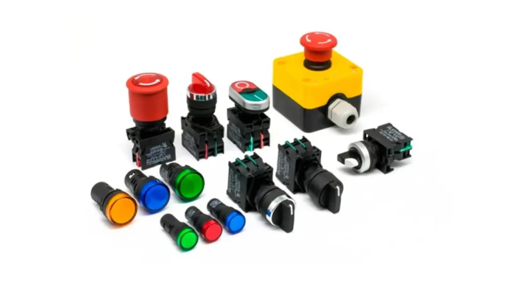
- Versatility: Available in many types (momentary, latching, illuminated) and configurations (2-pin, 3-pin, 5-pin, etc.), they suit diverse applications from doorbells to industrial control panels.
- Reliability & Durability: Designed for repeated use, many push button switches are built to withstand harsh environments, ensuring long-lasting performance.
- Safety: They are often incorporated into safety systems, such as emergency stop buttons, allowing for quick and critical control over machinery and circuits.
How to Wire a Push Button Switch?
Now, let’s get to the core of it: how to wire a push button switch. This section will walk you through the practical steps, ensuring you can confidently connect your switch for various applications. Pay close attention to pin identification and power connections for safe and effective operation.
Tools Needed
To embark on your push button switch wiring project, having the right tools and materials at hand is crucial for efficiency and safety. Gathering these items beforehand will streamline the process and help prevent common wiring mistakes, ensuring a successful and reliable connection for your switch.
- Push Button Switch: Your chosen switch type (momentary, latching, illuminated, etc.).
- Wires: Appropriate gauge and insulation for your circuit’s voltage and current.
- Wire Strippers: For safely removing insulation from wire ends.
- Screwdrivers: If your switch or terminals use screw connections.
- Multimeter: Essential for checking continuity and troubleshooting connections.
- Power Source: A battery, power supply, or other power source matching your circuit’s voltage.
- Load: The device or component your switch will control (e.g., LED, motor, relay).
- Soldering Iron & Solder: If your switch or circuit requires soldered connections.
- Heat Shrink Tubing/Electrical Tape: For insulating exposed wire connections.
- Safety Glasses: To protect your eyes from stray wire clippings or solder splashes.
Step 1: Identify Your Switch’s Pins
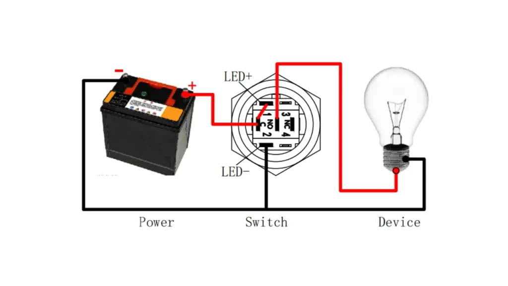
Before making any connections, carefully examine your push button switch to identify its terminals. Common markings include ‘C’ (Common), ‘NO’ (Normally Open), ‘NC’ (Normally Closed), and for illuminated switches, ‘+’ and ‘-‘ for the LED. Consulting the manufacturer’s datasheet or a diagram specific to your switch model is highly recommended for accurate identification.
Once pins are identified, you’ll know which connections correspond to the switching action and, if applicable, the LED illumination. This crucial first step dictates how the switch will interact with your circuit, determining whether it completes or breaks a connection, and how its integrated light behaves.
Step 2: Prepare Your Wires and Power Source
Strip a small amount of insulation from the ends of your wires, typically about 1/4 to 1/2 inch, using wire strippers. Ensure your power source (e.g., battery, power supply) is disconnected or turned off to prevent accidental short circuits or electric shock during the wiring process. Safety is paramount at this stage.
Having your wires prepped and power secured allows for clean, reliable connections. This preparation minimizes the risk of loose strands causing issues and ensures you can focus solely on correctly attaching each wire to its designated terminal without electrical hazards present.
Step 3: Connect the Power Source
For most circuits, you’ll connect one terminal of your power source (usually the positive side for the common connection in a simple circuit) to the ‘C’ (Common) pin of the push button switch. This establishes the primary input point for the electrical current that the switch will control. Ensure this connection is secure, either by soldering, using screw terminals, or appropriate connectors.
This connection acts as the gateway for power entering the switch. By linking the power source to the common pin, you provide the necessary electrical potential for the switch to either pass current through to the ‘NO’ or ‘NC’ contacts, depending on its type and actuation, thereby controlling your device.
Step 4: Wire the Load to the Switch
Next, connect the device you wish to control (your ‘load,’ such as an LED, motor, or relay) to the appropriate switch terminal. For a Normally Open (NO) circuit, connect your load to the ‘NO’ pin. When the button is pressed, the circuit will close, activating the load. For a Normally Closed (NC) circuit, connect to the ‘NC’ pin; the load will be active by default and turn off when pressed.
This step establishes the operational link between your switch and the controlled component. Choosing the correct NO or NC pin is vital for achieving the desired behavior—whether the device turns on with a press or turns off when the button is activated.
Step 5: Complete the Circuit to Ground
Finally, connect the other side of your load (or the return path from the switch, if the load is connected directly to the ‘NO’/’NC’ pin) back to the negative terminal of your power source, or to the common ground of your circuit. This completes the electrical loop, allowing current to flow when the switch is in the appropriate state.
Ensuring a complete circuit to ground is fundamental for any electrical setup. This final connection provides a return path for the current, enabling the switch to effectively control the flow of electricity to your device and allowing the entire system to operate as intended.
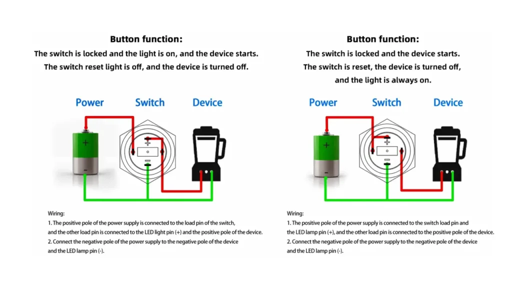
Step 6: Wire the LED (if applicable)
If your push button switch has an integrated LED, you’ll need to wire it separately. Connect the positive terminal of the LED (often marked with a longer leg or a ‘+’ sign, or specified in the datasheet) to your power source (possibly through a current-limiting resistor, depending on voltage). Connect the negative LED terminal to the circuit’s ground.
Properly wiring the LED ensures it illuminates without burning out, providing valuable visual feedback. Always use a current-limiting resistor if required by your LED’s voltage specifications, as direct connection to a higher voltage power source can damage the LED instantly.
Step 7: Test Your Connections
Once all wiring is complete and double-checked, carefully re-connect your power source. Test the functionality of your push button switch by pressing it. Verify that the load (and LED, if applicable) behaves as expected according to the type of switch (momentary/latching, NO/NC) and your wiring configuration.
Thorough testing is the final and most critical step to confirm your wiring is correct and safe. Observing the expected operation of your components ensures your hard work has paid off and that the circuit is functioning reliably and without issues.
How to Wire a Push Button Switch With 3 Wires
Wiring a 3-wire push button switch is straightforward once you understand its pin functions. These switches commonly feature Normally Open (NO) and Normally Closed (NC) contacts, providing versatility for various circuit control scenarios. This guide will walk you through the essential connections.
Step 1: Identify the Pins
Your 3-wire push button switch will typically have three terminals: Common (C or COM), Normally Open (NO), and Normally Closed (NC). The Common pin is where your input power usually connects. The NO pin connects when pressed, and the NC pin disconnects when pressed.
Step 2: Connect the Power Source
Begin by safely connecting the positive side of your power source (e.g., battery’s positive terminal or power supply’s output) to the Common (C or COM) pin of your push button switch. This supplies the necessary electrical current that the switch will then route based on its state.
Step 3: Choose Your Circuit Type
Decide whether you need a Normally Open (NO) or Normally Closed (NC) circuit for your application. An NO circuit activates the connected device when the button is pressed. An NC circuit deactivates the device when the button is pressed, with the device active by default.
Step 4: Wire the Load
If you chose a Normally Open (NO) circuit, connect your load (the device you want to control, like an LED or relay) to the NO pin. If you chose a Normally Closed (NC) circuit, connect your load to the NC pin.
Step 5: Complete the Circuit to Ground
Finally, connect the other end of your load to the negative terminal of your power source, or to the common ground of your circuit. This completes the electrical path, allowing current to flow through your load when the push button switch is activated as intended.
Step 6: Test Functionality
With all connections securely made, carefully re-introduce power to your circuit. Press the push button switch to verify that your load activates or deactivates precisely as expected, confirming your NO or NC wiring choice was correct and functional.
How to Wire a Push Button Start Switch?
Wiring a push button start switch allows for momentary activation of a circuit, commonly used to initiate devices like engines or control systems. Understanding its simple operation and correct connections is key to integrating it effectively and safely into your electrical projects.
Step 1: Identify Switch Terminals
A push button start switch is typically a momentary, Normally Open (NO) type. You’ll identify at least two terminals: a Common (C or COM) pin, where power enters, and a Normally Open (NO) pin, which connects to the Common when the button is pressed.
For switches with more pins, such as those with an internal LED, carefully consult the manufacturer’s diagram to distinguish between the switch’s operational pins (Common, NO) and the LED’s power pins, ensuring correct wiring for your intended start function.
Step 2: Connect Power Input
Begin by connecting the positive lead from your power source (e.g., vehicle battery positive, or power supply output) to the Common (C or COM) terminal of the push button start switch. Ensure this connection is secure and well-insulated, as it provides the main electrical input for the switch.
This direct connection to the power source establishes the foundational input for the switch. When activated, the switch will then momentarily direct this power to your desired starting component, making this initial power connection critical for the entire system’s functionality.
Step 3: Connect to the Load/Starter Component
Next, connect the Normally Open (NO) terminal of the push button switch to the positive input of the device you want to “start.” This might be a relay coil, a starter solenoid’s trigger wire, or the control input of an electronic module that initiates the desired action.
This connection routes the power from the switch to the actual starting mechanism. When you press the button, power flows from the Common pin through the closed NO contact, directly activating your load or sending the signal to your control system for initiation.
Step 4: Complete the Circuit
Finally, ensure your load or starter component has a complete circuit. Connect the other side of your load (its negative or ground connection) back to the negative terminal of your power source or the system’s chassis ground. This allows current to flow when the switch is activated.
Completing the circuit provides the necessary return path for the electrical current. Without this connection, even if the switch activates, the current cannot flow fully through the load, and your “start” action will not be successfully executed.
Step 5: Test the Start Function
With all wiring secured and power connected, perform a test. Press the push button start switch momentarily. Observe if the intended device or system initiates correctly (e.g., a relay clicks, an engine cranks briefly, or a control sequence begins).
Thorough testing confirms that your wiring is correct and safe for operation. This step ensures that the momentary activation of the switch successfully triggers the desired starting action, providing confidence in your electrical setup.
Momentary Push Button Switch Wiring
Momentary push button switches are designed to create a temporary electrical connection, or break an existing one, only while the button is actively being pressed. As soon as the pressure is released, the switch returns to its original, default state (either open or closed). Wiring these switches is straightforward, typically involving a Normally Open (NO) configuration for activation.
- Temporary Action: Only activates the circuit for the duration of the press.
- Common Use: Ideal for triggers, resets, doorbells, and start buttons.
- Simple Wiring: Often uses just two terminals (Common and Normally Open).
- NO Configuration: Power connects to one terminal, load to the other; pressing closes the circuit.
- Safety: Ensures systems only operate while actively commanded.
Push Button Wiring Considerations
Beyond the basic connections, several critical considerations are paramount when wiring any push button switch to ensure safety, reliability, and optimal performance. Neglecting these factors can lead to malfunctions, damage to components, or even hazardous conditions, making careful planning and execution essential for every project.
- Voltage and Current Ratings: Always match the switch’s specifications to your circuit’s requirements to prevent overheating or failure.
- Normally Open (NO) vs. Normally Closed (NC): Understand the default state of your switch and select the correct contact type for your intended circuit behavior.
- Wire Gauge: Use wires of appropriate thickness for the expected current draw to avoid voltage drop and overheating.
- Insulation and Secure Connections: Ensure all exposed wires are properly insulated and connections are tight to prevent short circuits and ensure longevity.
- Environmental Factors: Consider operating temperature, humidity, and potential exposure to dust or water when selecting switch IP ratings and wiring methods.
- Switch Type (Momentary/Latching): Verify the switch’s action matches your application’s control logic.
Conclusion
You’ve now mastered the essential techniques for wiring push button switches, from understanding their diverse types and pin configurations to executing precise connections for both basic and illuminated models. This fundamental skill unlocks a vast array of possibilities, empowering you to bring your electronic projects to life with reliable and intuitive control.
By applying the step-by-step guidance provided, you can confidently integrate push button switches into various applications, ensuring safe and effective operation. Remember, practice and attention to detail are key to successful wiring and robust circuit design.
For your next project requiring high-quality components, consider exploring wholesale push button switches from Linkwell Electrics. They offer a wide range of reliable options to meet your specific needs, helping you source the perfect switches for any scale of production or personal endeavor.