Embarking on electrical projects often involves the crucial step of junction box wiring. These unassuming enclosures serve as central connection points, ensuring safe and organized distribution of electrical power throughout your home. Understanding the fundamentals of how to properly wire within a junction box is paramount for any DIY enthusiast or homeowner tackling Electrical Enclosure tasks.
This blog will demystify the process of junction box wiring, breaking down the essential concepts and techniques. We’ll explore the basics of wire connections, safety considerations, and best practices to help you confidently navigate your electrical projects. Mastering junction box wiring is a foundational skill for ensuring the reliability and safety of your home’s electrical system.
What is Junction Box Wiring

Junction box wiring refers to the process of making electrical connections within an enclosure designed to protect these connections from the environment and accidental contact.
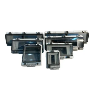
Junction Box VS Outdoor Enclosure
| Feature | Electrical Box | Junction Box | Outdoor Enclosure |
|---|---|---|---|
| Nature | Generic Base Category | A Specific Functional Type of Electrical Box | A Specialized Housing for Harsh Environments |
| Core Internal Components | A single device or termination point. e.g., a switch, a receptacle, a light fixture base. | Wire connections and splices for multiple circuits. e.g., wire nuts, terminals, cable/conduit entries. | Complete devices, systems, fan, or modules. e.g., transformer, circuit breakers, PLC, network switch, terminal blocks, power supply. |
| Primary Purpose | To mount and protect a single electrical device and provide a safe, code-compliant base. | To safely contain and isolate live electrical connection points within a circuit, preventing shock and fire. | To provide comprehensive environmental protection (against weather, dust, impact, tampering) for sensitive equipment. |
| Simple Analogy | A single socket on a power strip. | The internal wiring and connections inside the power strip. | The plastic casing that protects the entire power strip’s internal parts. |
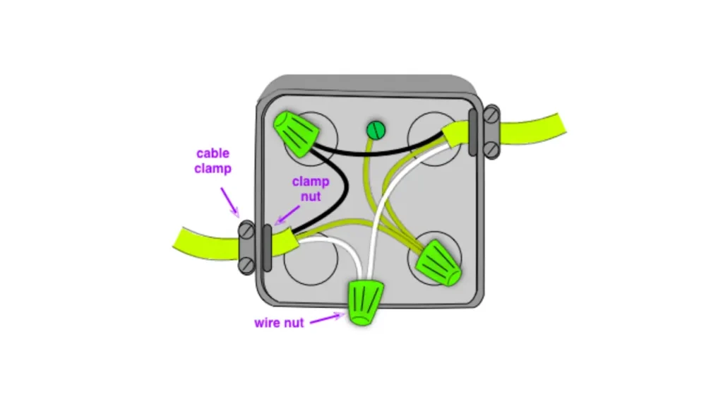
A junction box serves as a central point where multiple wires are joined together to distribute power to various outlets, lights, or appliances. Proper wiring within a junction box is crucial for a safe and functional electrical system, ensuring that connections are secure, insulated, and correctly grounded according to electrical codes.
The primary purpose of junction box wiring is to create a safe and organized point for electrical connections that would otherwise be exposed. By containing these connections within a protective box, the risk of electrical shock, short circuits, and fires is significantly reduced.
Junction boxes also provide a degree of protection against physical damage to the wires and connections. Furthermore, they make it easier to access and troubleshoot wiring issues in the future, as all the relevant connections for a particular part of the circuit are located in one identifiable place.
How Many Wires in a Junction Box
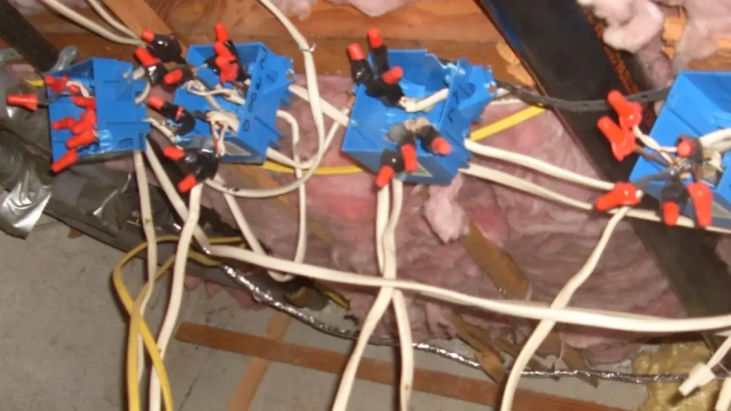
The number of junction box wires you can safely and legally put in a junction box isn’t a fixed number; it depends on the box’s size (volume in cubic inches) and the gauge (thickness) of the wires. Overfilling a junction box is a serious safety hazard as it can lead to overheating, short circuits, and fires. Electrical codes, specifically the National Electrical Code (NEC) Section 314.16, dictate the maximum number of conductors allowed in a box based on its volume and the size of the wires.
To determine the correct number of wires for a specific junction box, you need to calculate the “box fill.” Each conductor entering the box counts towards this fill, and different wire gauges have different volume allowances. Additionally, devices like switches and receptacles also contribute to the box fill calculation. It’s crucial to consult the NEC guidelines or use a box fill calculator to ensure you are within the code-compliant limits for your specific situation. Many junction boxes have their cubic inch capacity stamped inside, which is the first piece of information you’ll need for this calculation.
Here’s a simplified table illustrating the volume allowance per conductor size according to the NEC:
| Wire Gauge (AWG) | Volume Allowance (cubic inches) |
| 18 | 1.50 |
| 16 | 1.75 |
| 14 | 2.00 |
| 12 | 2.25 |
| 10 | 2.50 |
| 8 | 3.00 |
| 6 | 5.00 |
Keep in mind that this table only addresses the volume of the wires themselves. You also need to account for cable clamps, grounding conductors (counted as one based on the largest ground wire), and devices when calculating the total box fill. Always prioritize safety and adhere to the NEC or your local electrical codes when wiring junction boxes.
How to Wire a Junction Box

Wiring a junction box correctly is a fundamental skill for anyone undertaking electrical projects, whether it’s adding a new light fixture, extending a circuit, or replacing an outlet. A properly wired junction box ensures safe and reliable electrical connections, protecting against shorts, fires, and electrical shocks.
This guide will walk you through the essential steps for safely and effectively wiring a junction box. Always remember to turn off the power to the circuit you’ll be working on at the main electrical panel before starting any electrical work.
Step 1: Preparation and Safety First
Before you begin, the most critical step is to ensure the power to the circuit you’ll be working on is completely turned off at the main electrical panel. Locate the correct breaker and switch it to the “off” position. It’s wise to double-check with a non-contact voltage tester to confirm that no power is present in the wires you’ll be handling.
Gather all necessary tools, including wire strippers, screwdrivers (various types), wire connectors (various sizes), pliers, and safety glasses. Ensure you have the correct type and size of junction box for your application and that it’s securely mounted.
Step 2: Identifying the Wires
Once the power is off and you’ve accessed the inside of the junction box, carefully identify the different wires. Typically, you’ll encounter black wires (hot), white wires (neutral), and bare copper or green wires (ground).
In some older wiring, you might find different colors, so it’s essential to understand their function. If you’re unsure, consulting a wiring diagram or a qualified electrician is recommended. Separate the wires gently and ensure you have enough working length to make secure connections.
Step 3: Stripping the Wire Ends
Using your wire strippers, carefully remove a section of the plastic insulation from the ends of each wire that needs to be connected. The amount of insulation to remove will depend on the size of the wire and the type of wire connectors you’re using; a good rule of thumb is about 1/2 to 3/4 of an inch.
Be careful not to nick or damage the copper conductors while stripping, as this can weaken the wire and lead to potential problems.
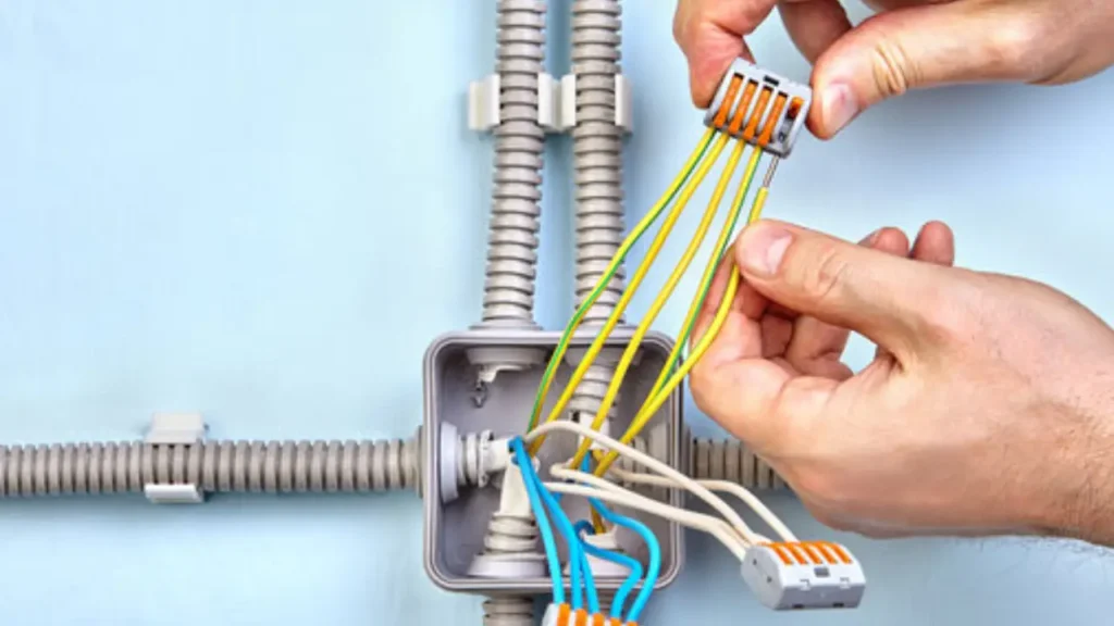
Step 4: Making the Connections
Now, you’ll begin connecting the wires according to their function. Typically, all the black (hot) wires that need to be joined together in the box will be twisted together clockwise using pliers, and then a wire connector (like a twist-on wire nut) will be screwed onto the twisted ends.
Repeat this process for all the white (neutral) wires that need to be joined. For the ground wires (bare copper or green), they should all be connected together and, in a metal junction box, also connected to the grounding screw inside the box. Ensure all wire connectors are tightly secured to create a solid electrical connection.
Step 5: Securing the Wires and Tidying Up
After making all the necessary connections, carefully fold the connected wires and tuck them neatly into the junction box. Avoid bending the wires sharply, as this can cause damage.
Ensure that the wire connectors are not loose and that no bare wire is exposed outside the connectors. The goal is to have the wires organized within the box so that they don’t interfere with the installation of a cover plate or a fixture.
Step 6: Installing the Junction Box Cover
Once the wires are safely connected and tucked inside the box, it’s crucial to install the appropriate cover plate. The cover protects the wiring from physical damage and prevents accidental contact with live wires.
Choose a cover that is the correct size and shape for your junction box and secure it tightly with screws. Remember that all junction boxes must remain accessible and cannot be covered by insulation or drywall.
Step 7: Final Check and Restoring Power
Before restoring power to the circuit, double-check all your connections to ensure they are secure and that the cover plate is properly installed. Make sure no tools or stray wires are left inside the box.
Once you are confident in your work, you can carefully turn the circuit breaker back on at the main electrical panel and test any connected devices or fixtures to ensure they are functioning correctly. If anything doesn’t work as expected, immediately turn off the power again and re-examine your wiring. If you are unsure about any step, it’s always best to consult a qualified electrician.
Junction Box Wiring Guidelines
Here are some key guidelines to keep in mind when wiring a junction box to ensure safety and code compliance. Always begin by de-energizing the circuit and verifying it’s off with a voltage tester. Inside the box, ensure all wire connections are secure using appropriately sized wire connectors, twisting stranded wires together clockwise before applying the connector. Each wire should be fully inserted into the connector, and the connector should be twisted on firmly.
Another crucial aspect is proper grounding. All ground wires (typically bare copper or green) within the junction box must be connected together and, in metal boxes, also connected to the grounding screw provided in the box.
This grounding provides a safe path for fault currents. Additionally, ensure that the correct size and type of junction box are used for the number and gauge of wires being connected, avoiding overcrowding which can lead to overheating. Finally, always secure the junction box cover tightly after wiring to protect the connections and prevent accidental contact.
Here are some important junction box wiring guidelines:
- De-energize the circuit: Always turn off the power at the breaker before working on any wiring.
- Verify power is off: Use a non-contact voltage tester to confirm the circuit is dead.
- Use appropriate wire connectors: Select the correct size and type of connector for the number and gauge of wires.
- Secure connections: Twist stranded wires together clockwise before applying connectors and ensure a tight fit.
- Proper grounding: Connect all ground wires together and to the grounding screw in metal boxes.
- Avoid overcrowding: Use a junction box of adequate size for the number of wires.
- Secure cover: Always install and tightly fasten the junction box cover.
How to Identify Wires in Junction Box
Identifying the wires within a junction box is a crucial first step for any electrical work, ensuring you connect the correct wires to maintain circuit integrity and safety. Before you even think about touching any wires, the absolute priority is to turn off the power to the circuit at the main electrical panel. Once the power is off, use a non-contact voltage tester to double-check that no wires in the box are live. Only then can you safely proceed with the identification process.
Visual Inspection and Color Coding
Begin by visually inspecting the wires inside the junction box. In modern wiring, the colors typically indicate their function: black or red are usually hot wires (carrying power), white is generally neutral (carrying current back), and green or bare copper is the ground wire (for safety). However, be aware that older wiring might not strictly adhere to these color codes, so visual identification alone is not always reliable. Look for any markings or labels on the wires as well.
Tracing Wires (If Possible)
If the wiring is relatively straightforward and you have access to both ends of the circuit, you might be able to trace wires back to their source or destination. For instance, if you’re working on a light fixture, you might be able to see which wires in the junction box correspond to the wires connected to the fixture. This can help confirm the function of each wire, especially if the color coding is unclear or if it’s older wiring.
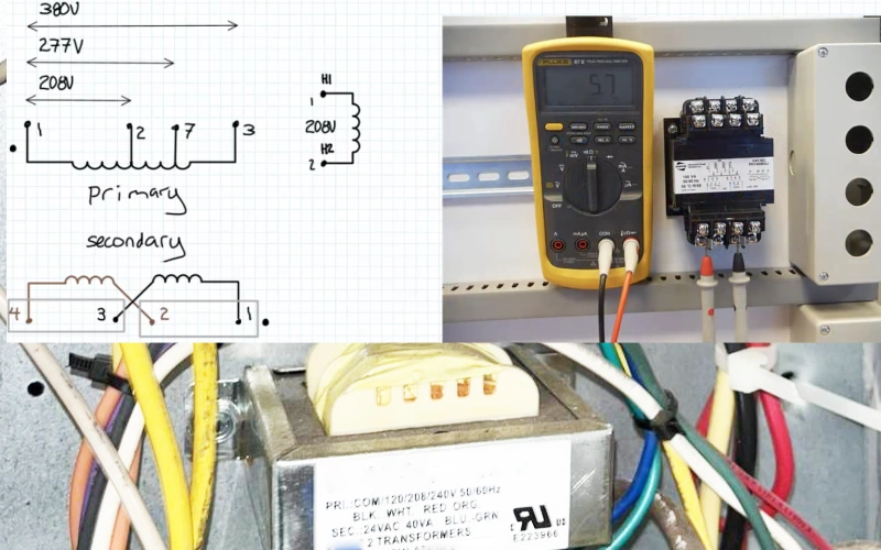
Using a Multimeter (Voltage Tester)
Once you’ve visually inspected the wires and traced them if possible, the most reliable way to identify them is by using a multimeter or a voltage tester. Even after turning off the breaker, it’s crucial to confirm the absence of voltage. Then, if you’re trying to identify which wire is the hot wire when the power is on (only do this if you are absolutely sure you know what you’re doing and are taking extreme safety precautions, otherwise call an electrician), you would carefully test each wire against a known neutral or ground to see if it registers voltage when the breaker is on.
Labeling the Wires
Once you have positively identified each wire, it’s a good practice to label them. You can use electrical tape of the corresponding color (e.g., black tape for hot, white tape for neutral, green tape for ground) or commercially available wire labels. This is especially helpful if you’re working on a complex wiring setup or if you might need to revisit the junction box in the future. Clear labeling reduces the risk of errors during reconnection.
Documenting Your Findings
Finally, it’s always a good idea to document your findings, especially for more involved electrical projects. You can create a simple diagram or take notes on which wire connects to where. This documentation can be invaluable if you need to troubleshoot issues later or if someone else needs to work on the wiring in the future. Having a clear record can save time and prevent potential mistakes. Remember, if you are ever unsure about identifying wires, it’s always best to consult a qualified electrician.
Electrical Junction Box Wiring Code
The National Electrical Code (NEC) sets specific standards for wiring within electrical junction boxes to ensure safety and prevent hazards.
All wire connections must be contained within an approved junction box (NEC 300.15). The junction box must be of sufficient size to accommodate all conductors and devices without overcrowding (NEC 314.16), and it must be securely mounted (NEC 314.23). Proper grounding of all metal boxes is essential to provide a path for fault currents (NEC 250.110).
Furthermore, the NEC mandates that all junction boxes must remain accessible after installation without requiring the removal of any part of the building structure or finish (NEC 314.29). This accessibility is crucial for future inspection, maintenance, and modifications. Wires entering the box must be protected from abrasion and secured with cable clamps or conduit fittings (NEC 314.17). Following these guidelines is vital for a safe and code-compliant electrical installation.
Here are key aspects of the electrical junction box wiring code:
- Containment: All splices and connections must be within an approved junction box (NEC 300.15).
- Junction Box Fill: The box must be large enough for the number and size of conductors and any devices (NEC 314.16).
- Secure Mounting: Junction boxes must be rigidly and securely fastened (NEC 314.23).
- Grounding: Metal boxes must be properly grounded (NEC 250.110).
- Accessibility: Boxes must remain accessible without damaging the building (NEC 314.29).
- Wire Protection: Wires entering the box must be secured and protected (NEC 314.17).
Conclusion
Mastering the fundamentals of junction box wiring is a cornerstone of safe and effective electrical projects. A solid understanding of wire connections, proper techniques, and adherence to safety guidelines empowers both DIY enthusiasts and seasoned professionals. This knowledge ensures reliable power distribution and minimizes the risk of electrical hazards within any wiring system.
This guide has illuminated the essential aspects of junction box wiring, providing a foundation for tackling various electrical tasks with confidence. By grasping these basics, you can approach your projects with greater clarity and competence, leading to successful and secure outcomes. Remember, accuracy and safety should always be your top priorities when working with electricity.
For projects requiring specialized enclosures, consider our comprehensive range. Get custom junction boxes tailored to your specific needs from Linkwell Electrics, ensuring optimal performance and seamless integration for all your electrical endeavors.