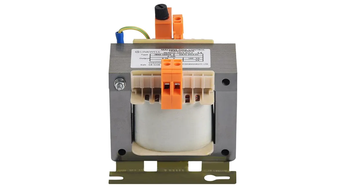
Wiring a control transformer correctly is fundamental to ensuring the safe and reliable operation of control circuits. These transformers step down higher voltages to lower, safer levels required by control components. Understanding the basic wiring configurations, whether for single or dual primary voltage setups, is essential for proper installation.
This blog will guide you through the essential steps and considerations for wiring a control transformer effectively. We’ll cover how to connect the primary and secondary windings based on your specific voltage requirements and highlight crucial safety precautions to follow during the process. Correct wiring guarantees the intended voltage output and protects both equipment and personnel.
Why Need to Wire Control Transformer?
Wiring a control transformer is a fundamental step in establishing a safe and reliable power supply for control circuits within industrial and commercial equipment. These transformers are essential for stepping down higher voltage levels, commonly found in power distribution systems, to the lower voltage requirements of sensitive control components such as relays, contactors, sensors, and programmable logic controllers (PLCs). Without proper wiring, these control devices would be subjected to damaging voltage levels, leading to malfunction or complete failure.
The necessity of wiring control transformers stems from several key reasons:
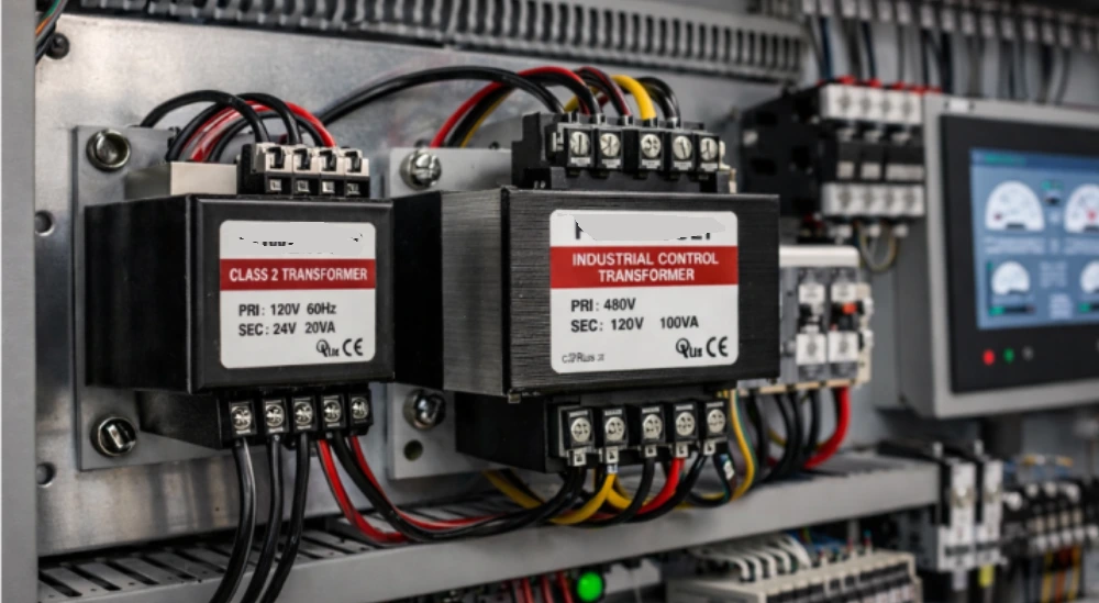
- Voltage Transformation: Control circuits typically operate at lower voltages (e.g., 24VAC, 120VAC) than the available power supply (e.g., 240VAC, 480VAC). Wiring the transformer correctly allows for the necessary voltage step-down to match the requirements of the control devices.
- Electrical Isolation: Control transformers provide galvanic isolation between the primary (high-voltage) and secondary (low-voltage) sides. This isolation enhances safety by preventing high-voltage faults from propagating to the control circuit and protecting personnel and sensitive equipment.
- Circuit Protection: Proper wiring often includes the incorporation of fuses or circuit breakers on both the primary and secondary sides of the control transformer. This vital protection safeguards the transformer and the connected control components from overcurrent conditions and short circuits.
How to Wire a Control Transformer?
Wiring a control transformer correctly is crucial for ensuring the safe and reliable operation of control circuits. This process involves understanding the transformer’s terminal markings, connecting the primary side to the appropriate high-voltage source, and wiring the secondary side to the control components at the desired lower voltage. Always ensure the power source is disconnected before beginning any wiring work.
Step 1: Identify Terminals and Wiring Diagram
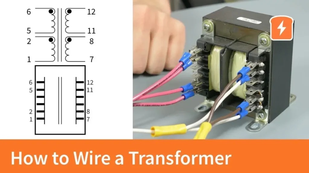
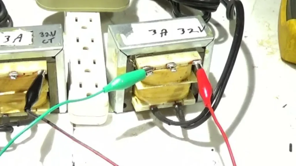
Begin by carefully examining the control transformer itself. The primary and secondary terminals are typically labeled with markings such as H1, H2 (for primary) and X1, X2 (for secondary). Locate the manufacturer’s wiring diagram, which is usually found on the transformer’s casing or a separate datasheet. This diagram is essential as it illustrates the correct connections for the desired input and output voltages. Understanding the terminal designations and the wiring diagram is the first critical step towards a successful and safe installation.
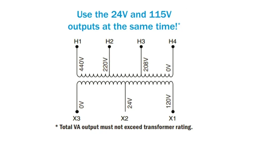
The wiring diagram will show how to connect the primary windings for different input voltages. For dual-voltage transformers, it will illustrate whether to connect the primary coils in series (for higher voltage) or parallel (for lower voltage). Similarly, the diagram will show the connections for the secondary winding to achieve the specified output voltage. Pay close attention to the polarity markings on the terminals, especially for more complex wiring configurations or when dealing with multiple secondary windings.
Step 2: Wire the Primary Side
Once you understand the terminal markings and the wiring diagram for your specific input voltage, proceed to wire the primary side of the transformer. Using appropriately sized wires, connect the incoming high-voltage power source to the designated primary terminals (H1 and H2). Ensure that the wire connections are secure and that the terminal screws are tightened properly to prevent loose connections, which can cause overheating and electrical issues.
It is highly recommended to install overcurrent protection, such as a fuse or circuit breaker, on the primary side of the control transformer. This protection device should be sized appropriately for the transformer’s primary current rating and will help to protect the transformer from faults on the primary side. Mount the fuse holder or circuit breaker in an easily accessible location for future maintenance or troubleshooting.
Step 3: Wire the Secondary Side
After wiring the primary side and ensuring it is properly protected, move on to wiring the secondary side of the control transformer. Connect the control circuit components to the designated secondary terminals (X1 and X2), using wires of the appropriate size for the expected current draw of the control circuit. Again, ensure all connections are secure and terminals are tightened.
Just like the primary side, it is crucial to provide overcurrent protection on the secondary side of the control transformer. Install a fuse or circuit breaker sized according to the maximum current the secondary circuit is designed to carry and the transformer’s secondary current rating. This protection will safeguard the control components and the transformer from faults on the secondary side.
Step 4: Grounding and Final Checks
Proper grounding is essential for safety. Ensure that the transformer’s frame is properly grounded according to local electrical codes. This provides a path for fault currents to flow to the ground, helping to prevent electrical shock hazards.
Before energizing the control transformer, double-check all wiring connections against the manufacturer’s wiring diagram. Verify that the primary and secondary sides are wired correctly for the intended input and output voltages and that all terminals are securely fastened. Ensure that all safety precautions have been taken and that the surrounding area is clear before applying power to the transformer.
How Do You Connect Electrical Wires to a Transformer?
Connecting electrical wires to a transformer requires careful attention to the terminal markings and the intended voltage configuration. Always ensure the power supply is completely disconnected before starting any wiring to prevent electrical shock. The process generally involves identifying the primary and secondary terminals, understanding the wiring diagram for the desired voltage, securely attaching the appropriately sized wires to the terminals, and ensuring proper grounding for safety.
Step 1: Identify Terminals and Wiring Diagram
Begin by locating the transformer’s terminal markings, typically labeled as H1, H2 (primary) and X1, X2 (secondary), and the manufacturer’s wiring diagram, often found on the unit or its datasheet. The diagram illustrates how to connect the primary windings for different input voltages (series for higher voltage, parallel for lower) and the secondary windings for the desired output voltage. Understanding these markings and the diagram is crucial for correct and safe wiring.
Step 2: Connect the Primary Side
Once the terminals and wiring diagram are understood, connect the incoming power supply wires to the primary terminals (H1 and H2) using appropriately sized conductors. Ensure a secure connection by tightening terminal screws adequately to prevent loose connections, which can cause overheating. It is also highly recommended to install a properly sized fuse or circuit breaker on the primary side for overcurrent protection of the transformer.
Step 3: Connect the Secondary Side
Next, connect the wires leading to the load or control circuit to the secondary terminals (X1 and X2), again using wires of the correct size for the expected current. Ensure these connections are also tight and secure. Similar to the primary side, it is advisable to install overcurrent protection (fuse or circuit breaker) on the secondary side to protect both the transformer and the connected devices from faults.
Step 4: Grounding and Final Checks
Proper grounding of the transformer frame is essential for safety, providing a path for fault currents. Connect a grounding conductor from the transformer’s ground terminal to a suitable ground point in accordance with electrical codes. Before energizing the transformer, meticulously double-check all wiring connections against the diagram to ensure accuracy and safety. Verify that all terminals are secure and the surrounding area is clear.
What Do H1 and X1 Mean on a Transformer?
On a transformer, the markings H1 and X1 are standard designations for specific terminals of the windings, following ANSI (American National Standards Institute) standards.
These markings are crucial for understanding the transformer’s polarity and ensuring correct wiring, especially when paralleling transformers or connecting them in circuits where phase relationships matter.
- H1: This terminal always denotes one end of the high-voltage winding (also known as the primary winding in step-down applications). According to ANSI standards, when facing the high-voltage side of a single-phase transformer, the H1 terminal is typically located on the left. It serves as a designated starting point or reference for the high-voltage winding’s polarity.
- X1: This terminal denotes one end of the low-voltage winding (also known as the secondary winding in step-down applications). The position of the X1 terminal relative to the H1 terminal indicates the transformer’s polarity (additive or subtractive). For subtractive polarity transformers, which are common for larger ratings, the X1 terminal is usually located on the same side as the H1 terminal.
Here’s a table summarizing the meaning of H1 and X1:
| Terminal | Winding | Voltage Level | Typical Location (Facing HV Side) | Significance |
| H1 | High-Voltage (H) | Higher | Left | One end of the high-voltage winding, reference for polarity. |
| X1 | Low-Voltage (X) | Lower | Same side as H1 (subtractive) | One end of the low-voltage winding, its position indicates transformer polarity. |
Control Transformer Wiring Diagram
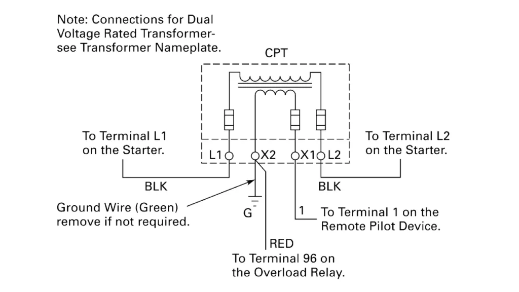
A control transformer wiring diagram is a schematic representation illustrating how to connect the transformer’s primary and secondary windings to the power source and the control circuit, respectively. These diagrams are essential for ensuring correct and safe installation. They typically show the transformer’s terminals, often labeled with H1, H2 for the high-voltage (primary) side and X1, X2 for the low-voltage (secondary) side, along with any additional terminals for dual-voltage configurations or center taps.
The wiring diagram will detail how to configure the primary windings for the specific input voltage available (e.g., series connection for higher voltage, parallel for lower voltage on dual-primary transformers). Similarly, it will show how the secondary winding should be connected to deliver the desired control voltage to the connected devices. Understanding these diagrams, including any symbols for fuses, circuit breakers, or grounding connections, is crucial for proper installation and troubleshooting of control transformers in industrial and commercial applications.
Conclusion
In conclusion, properly wiring a control transformer involves understanding its terminal markings, connecting the primary side to the correct voltage, and wiring the secondary side to the control circuit with appropriate fusing. Safety is paramount throughout the process, ensuring the transformer is de-energized during wiring and that connections are secure. Incorrect wiring can lead to malfunction or damage.
Following the manufacturer’s wiring diagram and adhering to electrical codes are essential for a successful installation. Taking the time to double-check connections before energizing the transformer can prevent costly errors and ensure the reliable operation of the control system. For businesses seeking quality components, Linkwell Electrics offers a range of wholesale control transformers.
Sourcing control transformers from reputable suppliers like Linkwell Electrics provides access to reliable products and potential cost savings for bulk purchases. Correct wiring, combined with quality transformers, is fundamental to building safe and efficient industrial and commercial control systems. Contact Linkwell Electrics for your wholesale control transformer needs.