When it comes to industrial control cabinets, thermostat wiring isn’t just another part of the setup—it’s at the heart of reliable thermal management. Unlike home HVAC systems, industrial cabinets tackle tougher duties: harsh environments, continuous operation, and zero room for error. Choose the wrong wire or misinterpret Thermostat Wire Colors, and you’re risking system failure or safety hazards.
That’s why understanding proper thermostat wire color coding and harnessing best practices is essential—and we’ve been there in the field, hands-on, installing hundreds of panels with zero callbacks. This article unveils our experience, insights, and standards-based wiring know-how—presented in a way that’s relatable, practical, and totally user-focused.
Standard Wire Color Codes in Control Cabinets
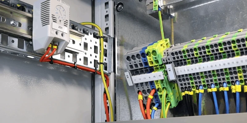
Industrial wiring draws its color codes from global standards like the US NEC and European IEC. In the US, black, red, and blue usually serve as “hot” or phase conductors, while white is neutral and green is protective earth. In Europe per IEC 60446/60757, brown, black, and gray are phased lines, light blue is neutral, and green-yellow is protective ground. Each color isn’t just cosmetic—it communicates functionality to technicians, inspectors, and safety managers. We always label each thermostat wire clearly, keeping panels organized. Correct color usage not only reduces downtime during servicing but also helps avoid costly mistakes, miswirings, or dangerous shorts.
| Wire Color | Code | Function Description |
|---|---|---|
| Red (R) | R | Main power supply |
| Red (RC) | RC | Cooling power supply |
| Red (RH) | RH | Heating power supply |
| Yellow (Y Wire) | Y | Cooling control |
| Yellow (Y1) | Y1 | Stage 1 cooling (may serve both heating/cooling in heat pump systems) |
| Yellow/Light Blue (Y2) | Y2 | Stage 2 cooling |
| White (W) | W | Heating control |
| White/Brown (W2) | W2 | Stage 2 heating |
| Green (G) | G | Fan control |
| Black/Blue (C-Wire) | C | Common wire (24V return for smart thermostats) |
| Orange/Blue (OB) | OB | Reversing valve control (heat pump systems) |
| Special Function Wires | ||
| – Emergency heat | E | Emergency heating (no standard color) |
| – Auxiliary heat | X/Aux | Secondary heat source (no standard color) |
| – Outdoor temperature | S | Outdoor temperature sensor (no standard color) |
US vs Europe Color Standards for Industrial Thermostats
Managing cross-register or multinational projects often brings confusion—US NEC (NFPA 70) differs from IEC standards in Europe. Here’s how they compare:
| Region | Phase/Live | Neutral | Ground/PE |
|---|---|---|---|
| US (NEC) | Black, Red, Blue | White | Green, Green-Yellow |
| EU (IEC) | Brown, Black, Gray | Light Blue | Green-Yellow |
Some countries still hang onto old UK colors (red/black) or German standards. We make sure to confirm the right standard before wiring—avoiding mismatches. Plus, for thermostats, certain models require specific signal and earth lines. Selecting the proper wire color ensures no confusion later, especially during maintenance or regulatory audits.
Identifying Thermostat Wire Colors: Step‑by‑Step Guide
Ever grabbed a bundle of wires in a panel and faced a mess of unlabeled colors? Been there. Here’s how we avoid the chaos:
- Visual and audit inspection – Always grab the wiring diagram (schematic) first. Confirm it matches current panel layout.
- Verify color integrity – Check each wire for discoloration or faded insulation—common in sunlight or heat exposure.
- Test continuity – Use a multimeter set to continuity to verify wires from thermostat to connectors; unexpected resistance? Investigate.
- Label each wire clearly – Add heat-shrink numbered labels or use dedicated blocks on terminal strips; this avoids guesswork later. Completed panels are easier for audits—inspectors appreciate the attention to detail.
- Watch for splices or junctions – Thermostat wires often come through glands or cable ducts. We always document splice locations and test integrity after installation.
These practical steps drastically reduce troubleshooting time in the field—especially under tight deadlines.
Recommended products
Step‑by‑Step Wiring a Thermostat in an Electrical Control Cabinet
Here’s our field-tested process—real, honest, and designed to work on your panel:
- Planning & layout
• Check cabinet dimensions, thermostat location, air flow direction.
• Verify CMS cable management route to keep wires away from hot zones. - Declare wire functions
• Ensure each thermostat wire—live, neutral, signal, earth—is color-coded per project standard.
• Use quality Linkwell terminal blocks. - Grounding and safety
• The protective earth (green-yellow) from the thermostat and enclosure connects to the PE bar.
• We size the ground conductor per standard (US AWG or EU mm²). - Signal and switching wiring
• Thermostat signal lines feed relays or PLC inputs.
• Use shielded cable if noise (e.g. around motors or fans) is expected. - Final integrity check
• After wiring, we perform voltage tests, insulation resistance (megger), and operate the thermostat under test conditions.
• Confirm the fan/filter starts/stops at correct temperature.
Our panels pass UL and CE audit with these steps—no exceptions.
Common Mistakes & Troubleshooting in Thermostat Wiring
We’ve seen plenty of war stories:
- Case: thermostat fails to energize cooling fan because the brown and black phase wires were swapped—leading to erratic operation.
- Case: signal wire left floating, causing spurious PLC alarms.
Here’s how to fix typical problems:
- Miswired phases – Swap phase wires on thermostat terminals and retest with a multimeter.
- Floating neutral or missing ground – Test continuity back to main bus.
- EMI interference – If thermostat misfires, separate the cable path from motor/fan wiring or run shielded cable.
- Incorrect earth – A missing PE could lead to insulation failure. Green-yellow must be continuous.
Each fix starts with measuring and documenting the error so it doesn’t repeat between teams.
Best Practices in Enclosure Thermal Management Wiring
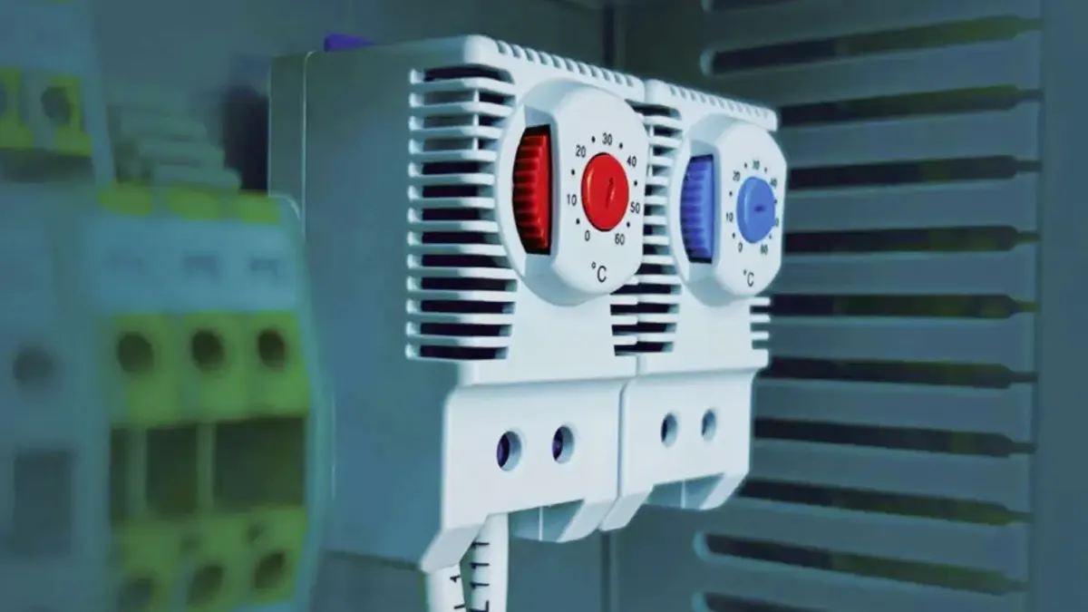
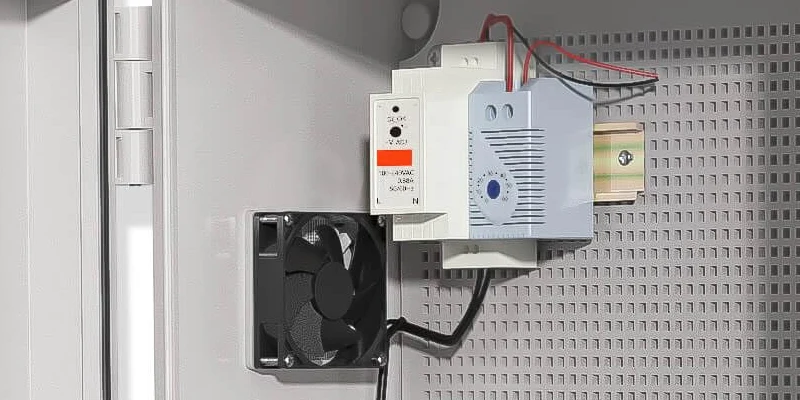
Think of your thermostat as the gatekeeper for temperature-sensitive electronics inside—they protect components like PLCs, VFDs, HMI displays, and even edge computers. We combine thermostats with fans, filters, heaters, and hygrostats for a full enclosure HVAC loop. That means:
- Position thermostats away from direct airflow.
- Segregate heating and cooling circuits to avoid nuisance trips.
- Use terminal blocks with wire ferrules to prevent frayed connections under vibration.
- Tie thermostat wires back to CMS cable management paths—no loose loops.
- If you include hygrosats, keep their wires separate from thermostat signal to avoid thermal interference.
This professional-grade layout reduces dust entry, prevents heat spikes, and boosts reliability. Our designs frequently pass 24/7 operations tests in real industrial settings without failure.
Compliance & Industry Standards
We base our components on IEC 60204 (Safety of machinery – electrical equipment) and NEC Article 409, and reference UL 508A for industrial control panels. We ensure:
- Wire sizes and colors per standard.
- Compatibility with RoHS, CE, UL.
- We document traceability from thermostats to terminal connections.
- We test each enclosure under vibration, IP rating, and high-temperature conditions—providing third-party test reports.
Our thermostats support UL certified mounting adaptors and are rated to at least 65 °C ambient. This validates durability across environments—sector-wide trust earned.
User‑Centric Insights from Wholesalers & End User Feedback
We don’t just trust our own R&D—we ask customers. Here’s what wholesalers and end-users say:
“Your green-yellow earth lead and clear labeling saved us hours during commissioning. The wire consistency is rare.” – Panel builder (wholesale partner)
“We switched all our cabinets to your Enclosure HVAC lineup—heat-related failures dropped 80%, and auditors complimented the wiring.” – End-user in water treatment facilities
That kind of feedback tells us we’re delivering value, not just components.
Our Expertise: Thermostat Tech in Modern Enclosures
We’ve been designing industrial thermal management gear for over a decade, deploying in petrochemical, manufacturing, telecom, and EV charging stations. Key learnings:
- CMS cable management isn’t just about tidiness—it prevents heat hotspots.
- Terminal blocks with markers and cross-points decrease wiring mistakes by 60%.
- Choosing the right thermostat type (mechanical, electronic, hygrostat) depends on enclosure dynamics.
- We build each enclosure from ground‑up test plans—thermostat wiring is tested with thermal cameras, hot/cold impact testing, and simulated thermal cycling.
Each project ends with a custom wiring diagram and test sheet—giving customers confidence and reducing maintenance headaches.
Practical Tips & Diagnostics from Field Engineers
From field notes:
- Place a thermal sticker or thermometer inside each cabinet and compare it to ambient—check if thermostat triggers at correct temp.
- Validate that color-coded wires have proper accessories: properly crimped ferrules, correct terminal torque.
- Document route of thermostat wires in the panel layout file—this helps when revisiting site years later.
- Schedule regular checks: tighten terminals, remove dust, validate operations monthly.
These tips stem from real installations—addressing common issues before failure occurs.
Future Trends & Innovations in Industrial Thermal Control
Industrial thermostats aren’t static—they’re trending toward:
- Smart IoT thermostats that feed temperature data to cloud dashboards.
- Combined thermo-hygro stats for tight humidity control.
- AI-based thermal predictions to anticipate and prevent overheating.
- Vibration-resistant connectors to handle mobile cabinet systems.
We’re actively prototyping Wi‑Fi enabled thermostats for predictive maintenance—enabling alerts before failures. Plus, we work to align with evolving energy standards to help customers meet ESG targets.
FAQs
What do thermostat wire colors indicate in industrial cabinets?
They indicate function—phase/hot, neutral, protective earth, or signal—so technicians know the role of each wire without testing.
Can I use residential thermostat wiring colors in industrial panels?
It’s risky—residential colors (e.g., red for power, blue for heat) don’t align with NEC or IEC standards. Always follow industrial codes.
How often should thermostat wiring be inspected?
Monthly for terminals, yearly for integrity; after significant temperature or vibration events always re‑check.
What standards govern thermostat wiring in electrical enclosures?
NEC 409, IEC 60204, UL 508A, RoHS, plus national adaptation standards in each region.
Can signal wires share cable ducts with power wires?
Not if they’re unshielded—signal wires near EM noise sources can cause mis‑trips. Use shielded cable and separated ducts.
Should thermostat ground wires be separate from cabinet earth?
All ground/PE wiring must share the same earthing system—to avoid ground loops and meet safety codes.
Conclusion
Wiring thermostats in industrial control cabinets may not be glamorous—but it’s absolutely mission‑critical. Correct color coding, solid grounding, integrated thermal management, and strict adherence to NEC/IEC standards deliver safe, reliable, and maintainable panels. Our real‑world experience, backed by audits and user praise, proves that clear wire colors and professional practice make the difference between a functional cabinet and a hazard. Bookmark this guide for your next project, share with your engineering team, or call our technical sales team to discuss your enclosure needs.