
Welcome to our comprehensive guide on Control Transformer Rating: Understanding VA, Voltage, and Current. Selecting the correctly rated control transformer is paramount for the safe and efficient operation of industrial and commercial control systems. This blog will break down the essential specifications of VA (volt-amperes), voltage (both input and output), and current, explaining their significance and how they interrelate in determining the appropriate transformer for your application.
We’ll delve into how to interpret these ratings on a transformer’s nameplate and why understanding them is crucial to avoid overload, ensure stable power delivery to your control circuits, and ultimately prolong the lifespan of your equipment. By the end of this post, you’ll have a solid grasp of control transformer ratings and be better equipped to make informed decisions for your specific needs.
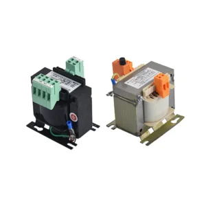
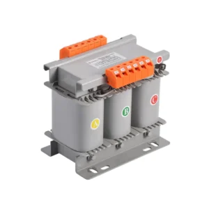
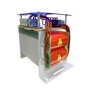
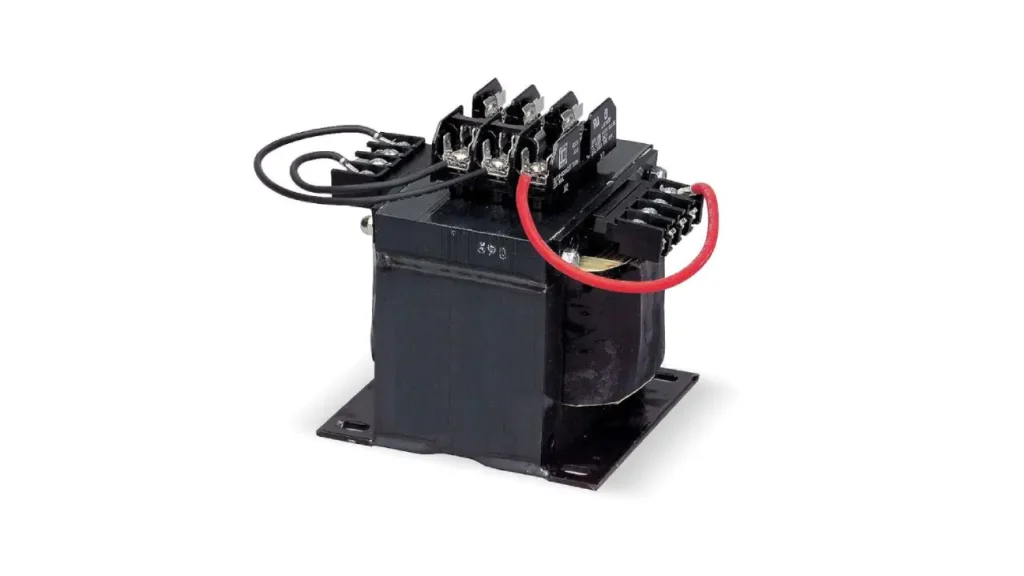
Recommended products

What Does a Control Transformer Rating Have?
Control transformer ratings encompass several key specifications that define its operational capabilities and limitations. Control transformers are rated in ratings; ratings are essential for selecting the appropriate transformer for a given control system to ensure both safety and reliable performance of the connected devices. Understanding each component of the rating is crucial for proper application.
The primary aspects included in a control transformer’s rating are:
- Volt-Ampere (VA) Rating: This indicates the apparent power the transformer can handle continuously without exceeding its temperature limits. It’s the product of the voltage and the current and represents the transformer’s capacity to supply power to the control circuit loads.
- Primary Voltage Rating: This specifies the voltage that should be applied to the primary winding of the transformer. It must match the voltage of the power source available to the system for the transformer to operate correctly.
- Secondary Voltage Rating: This indicates the voltage that the transformer is designed to output on its secondary winding when the rated primary voltage is applied. It must match the voltage requirements of the control devices being powered.
- Frequency Rating: This specifies the frequency of the AC power for which the transformer is designed to operate optimally, typically 50 Hz or 60 Hz. Using a transformer at a significantly different frequency can affect its performance and lifespan.
- Temperature Rating (Insulation Class): This indicates the maximum operating temperature the transformer’s insulation can withstand without degradation, influencing the transformer’s lifespan and the ambient temperature in which it can be installed.
What is Control Transformer Rating Used for?
Control transformer ratings, primarily given in volt-amperes (VA), voltage (primary and secondary), and current (amperage), serve a critical role in the selection and application of these transformers within control systems. These ratings provide essential information about the transformer’s capacity and operational limits, ensuring compatibility with both the power supply and the connected control circuit devices. Understanding these ratings is fundamental for safe and reliable operation.
Specifically, control transformer ratings are used for:
- Determining Power Handling Capacity (VA): The VA rating indicates the apparent power the transformer can supply without overheating. It’s crucial for matching the transformer’s capacity to the total power demand of the control circuit loads.
- Ensuring Voltage Compatibility: The primary voltage rating must match the available power supply voltage, while the secondary voltage rating must align with the operational voltage requirements of the control devices (e.g., relays, solenoids).
- Preventing Overcurrent and Overload: The current ratings (both primary and secondary) indicate the maximum current the transformer windings can safely handle. This information is vital for selecting appropriate overcurrent protection devices like fuses or circuit breakers to prevent damage to the transformer and the connected equipment.
- Predicting Performance Under Load: The voltage regulation characteristics, often associated with the VA rating, help predict how the secondary voltage will behave under varying load conditions, ensuring stable power delivery to the control circuit.
Control Transformer VA Rating
The VA (volt-ampere) rating of a control transformer indicates its apparent power capacity, which is the product of the voltage and current it can handle without overheating. This rating is crucial for selecting the appropriate transformer size to supply the total power demands of the connected control circuit loads, including resistive and inductive components. Ensuring the total VA of the control circuit does not exceed the transformer’s VA rating is essential for reliable operation and preventing premature failure.
The VA rating helps determine the transformer’s ability to handle both the steady-state power requirements and the temporary inrush currents drawn by inductive loads like solenoids and motor starters.
An adequately sized VA rating ensures the transformer can provide sufficient power without significant voltage drop during these inrush periods, which is vital for the proper functioning of control devices. Selecting a transformer with a VA rating that includes a safety margin above the calculated load further enhances performance and longevity.
Here are key aspects of the VA rating for control transformers:
- Power Capacity: Indicates the maximum apparent power the transformer can deliver continuously.
- Load Handling: Determines the total VA of control devices that can be safely connected.
- Inrush Consideration: Influences the transformer’s ability to handle temporary high current demands of inductive loads.
- Voltage Regulation: Affects how stable the output voltage remains under varying load conditions.
How to Calculate VA Rating of a Control Transformer?
Calculating the appropriate VA (volt-ampere) rating for a control transformer is a critical step in ensuring the reliable operation of your control system. This involves determining the total power demand of all connected devices, accounting for the unique characteristics of different load types, and applying a suitable safety margin to prevent overloading and ensure stable performance.
Step 1: Determine the VA of Resistive Loads
For resistive loads, such as pilot lights or heating elements within the control circuit, the VA rating is equivalent to their wattage (W). Simply sum the wattage of all resistive devices that will operate simultaneously. This provides the base power requirement contributed by the purely resistive components of your control system.
Step 2: Determine the VA of Inductive Loads
Inductive loads, like relays, solenoids, and motor starters, require more careful consideration. Their VA rating is typically provided on their nameplate and is often higher than their actual power consumption (wattage) due to the reactive power component. For each inductive device, use the VA rating specified on its label rather than just the wattage. Sum these VA values for all inductive devices that may operate concurrently.
Step 3: Account for Inrush Current of Inductive Loads
Inductive loads draw a significantly higher current, known as inrush current, when initially energized. To accommodate this temporary surge, multiply the total VA of the inductive loads (calculated in the previous step) by an appropriate inrush multiplier. This multiplier typically ranges from 2 to 4 or even higher, depending on the specific characteristics of the inductive devices. Adding this inrush VA to the resistive load VA provides a more accurate peak power demand.
Step 4: Apply a Safety Factor
After calculating the total VA, including the inrush current consideration, it’s essential to apply a safety factor. A common practice is to select a control transformer with a VA rating that is 20% to 25% higher than the calculated total VA. This safety margin provides a buffer for unexpected load increases, voltage fluctuations, and helps ensure the transformer operates within its thermal limits, prolonging its lifespan and improving voltage regulation.
Step 5: Select the Standard VA Rating
Control transformers are available in standard VA ratings (e.g., 50 VA, 75 VA, 100 VA, etc.). Once you have calculated the required VA with the safety factor, choose the next standard VA rating that is equal to or greater than your calculated value. This ensures that you select a readily available transformer with sufficient capacity for your control system’s needs.
How to Calculate Control Transformer Rating?
Calculating the appropriate VA (volt-ampere) rating for a control transformer is a critical step in ensuring the reliable operation of your control system. This involves determining the total power demand of all connected devices, accounting for the unique characteristics of different load types, and applying a suitable safety margin to prevent overloading and ensure stable performance.
Step 1: Determine the VA of Resistive Loads
For resistive loads, such as pilot lights or heating elements within the control circuit, the VA rating is equivalent to their wattage (W). Simply sum the wattage of all resistive devices that will operate simultaneously. This provides the base power requirement contributed by the purely resistive components of your control system.
Step 2: Determine the VA of Inductive Loads
Inductive loads, like relays, solenoids, and motor starters, require more careful consideration. Their VA rating is typically provided on their nameplate and is often higher than their actual power consumption (wattage) due to the reactive power component. For each inductive device, use the VA rating specified on its label rather than just the wattage. Sum these VA values for all inductive devices that may operate concurrently.
Step 3: Account for Inrush Current of Inductive Loads
Inductive loads draw a significantly higher current, known as inrush current, when initially energized. To accommodate this temporary surge, multiply the total VA of the inductive loads (calculated in the previous step) by an appropriate inrush multiplier. This multiplier typically ranges from 2 to 4 or even higher, depending on the specific characteristics of the inductive devices. Adding this inrush VA to the resistive load VA provides a more accurate peak power demand.
Step 4: Apply a Safety Factor
After calculating the total VA, including the inrush current consideration, it’s essential to apply a safety factor. A common practice is to select a control transformer with a VA rating that is 20% to 25% higher than the calculated total VA. This safety margin provides a buffer for unexpected load increases, voltage fluctuations, and helps ensure the transformer operates within its thermal limits, prolonging its lifespan and improving voltage regulation.
Step 5: Select the Standard VA Rating
Control transformers are available in standard VA ratings (e.g., 50 VA, 75 VA, 100 VA, etc.). Once you have calculated the required VA with the safety factor, choose the next standard VA rating that is equal to or greater than your calculated value. This ensures that you select a readily available transformer with sufficient capacity for your control system’s needs.
Primary Ampere Rating of Control Transformer
The primary ampere rating of a control transformer indicates the maximum current that the primary winding is designed to safely carry at its rated primary voltage. This control transformer primary ampere rating is crucial for selecting appropriate overcurrent protection devices, such as fuses or circuit breakers, on the primary side of the transformer.
These protective devices are essential to prevent damage to the transformer in the event of a fault or excessive current draw on the primary side.
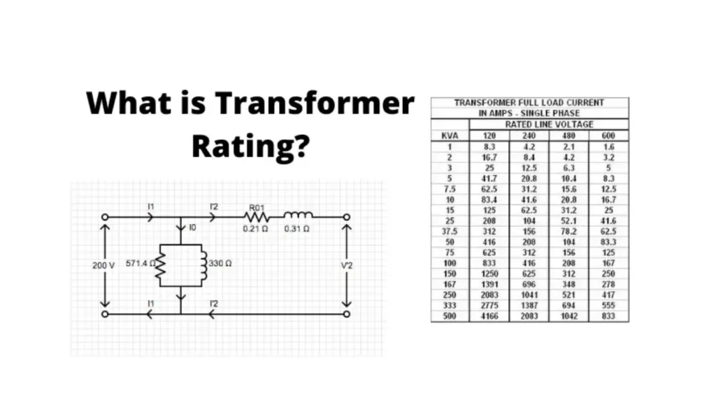
The primary ampere rating is directly related to the transformer’s VA rating and its primary voltage. It can be calculated using the formula: Primary Amperes (I_primary) = Transformer VA Rating / Primary Voltage (V_primary). Understanding this relationship is vital for ensuring that the primary circuit can adequately supply the necessary current to the transformer without overloading the wiring or the upstream protective devices.
Here are key aspects of the primary ampere rating for control transformers:
- Current Carrying Capacity: Specifies the maximum current the primary winding can handle without overheating.
- Overcurrent Protection: Used to determine the correct size of fuses or circuit breakers for the primary circuit.
- Source Capacity: Helps ensure the primary power source can supply the required current to the transformer.
- Wiring Size: Influences the selection of appropriate wire gauge for the primary connections to prevent excessive voltage drop and heating.
| Transformer VA Rating | Primary Voltage (Example) | Calculated Primary Amperes |
| 50 VA | 240 V | 0.21 A |
| 100 VA | 240 V | 0.42 A |
| 250 VA | 480 V | 0.52 A |
| 500 VA | 480 V | 1.04 A |
| 1000 VA | 240 V | 4.17 A |
Conclusion
In conclusion, understanding the VA, voltage, and current ratings of a control transformer is paramount for selecting the correct unit for your specific application. The VA rating dictates the transformer’s power-handling capacity, while the primary and secondary voltage ratings must match the supply and control circuit requirements, respectively. Finally, the current rating indicates the maximum current the transformer can safely deliver.
Carefully considering these three interconnected ratings ensures the reliable and safe operation of your control system, preventing overload and potential damage. Choosing the right control transformer based on these specifications is a critical step in system design and implementation. For businesses seeking a variety of options, Linkwell Electrics offers a range of wholesale control transformers.
Sourcing from reputable suppliers like Linkwell Electrics provides access to quality control transformers with clear and accurate ratings. By understanding and properly applying these ratings, you can optimize your control systems for efficiency and longevity. Contact Linkwell Electrics for your wholesale control transformer needs.