Overheating is a silent killer for dry-type transformers, leading to accelerated insulation degradation and ultimately, costly failures and unplanned downtime. Effective temperature monitoring is not merely a best practice; it’s a critical safeguard that actively extends the lifespan of your valuable electrical assets and ensures continuous operation.
This blog post will delve into the vital role of dry type transformer temperature monitoring as a proactive measure. By understanding and implementing robust monitoring strategies, you can prevent thermal damage, optimize performance, and significantly reduce the risk of unexpected outages, saving both time and considerable expense.
What is Dry Type Transformer Temperature Monitoring
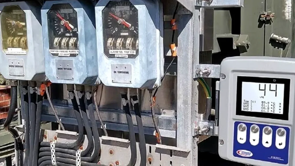
Dry type transformer temperature monitoring involves continuously tracking the temperature of the transformer’s windings and core to ensure it operates within safe thermal limits. This process typically utilizes various sensors like RTDs or thermocouples, integrated with local gauges or networked systems, to provide real-time data.
The goal is to detect abnormal temperature rises caused by overload, cooling system issues, or internal faults, thereby preventing insulation degradation, extending the transformer’s lifespan, and avoiding costly failures and unplanned downtime.
Dry Type Transformer Temperature Rise
Dry type transformer temperature rise refers to the difference in temperature between the transformer’s hottest spot and the ambient (surrounding) air temperature when operating under a specified load. This parameter is a critical indicator of the transformer’s thermal performance and directly impacts the lifespan of its insulation system. A lower temperature rise indicates a more efficient design in dissipating heat and less thermal stress on the insulation, leading to longer service life.
The temperature rise is governed by the transformer’s design, its cooling method, and the load it carries. Manufacturers typically specify a maximum permissible temperature rise (e.g., 80°C, 115°C, or 150°C), which is tied to the insulation class of the transformer. Exceeding this temperature rise consistently can significantly reduce the transformer’s lifespan, often following an inverse relationship where every 10°C increase above the rated temperature can halve the insulation’s life.
Key factors influencing and related to dry type transformer temperature rise include:
Load Current: Higher load currents lead to increased I²R losses in the windings, generating more heat and thus a higher temperature rise.
Core Losses: Hysteresis and eddy current losses in the magnetic core also contribute to heat generation.
Dry Type Transformer Cooling Method:
- Natural Air (AN): Relies on convection, generally resulting in higher temperature rises for a given load compared to forced air.
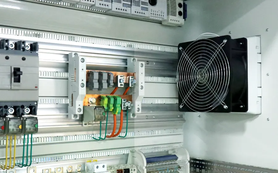
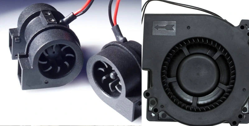
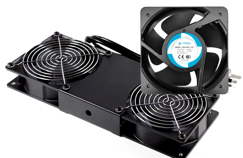
- Forced Air (AF): Utilizes fans to actively dissipate heat, allowing for lower temperature rises or higher KVA ratings for the same rise.
Ambient Temperature: The overall operating temperature is the sum of the ambient temperature and the temperature rise. High ambient temperatures mean less margin for temperature rise before reaching critical insulation limits.
Insulation Class: The maximum allowable temperature rise is limited by the transformer’s insulation class (e.g., Class H insulation can withstand higher temperatures than Class F).
Ventilation: Adequate ventilation around the transformer is crucial, even for AN units, to ensure proper airflow and heat removal, preventing localized hot spots.
Design Efficiency: The overall efficiency of the transformer design in converting electrical energy, minimizing losses that manifest as heat.
Dry Type Transformer Temperature Rise Calculation
Calculating the temperature rise in a dry-type transformer is a complex engineering task that involves understanding various heat generation and dissipation mechanisms. While simplified calculations can provide a general idea, precise determination often requires sophisticated thermal modeling and empirical testing.
The fundamental principle behind temperature rise calculation is the thermal balance equation: the heat generated within the transformer must be dissipated to the surrounding environment. If the heat generated exceeds the heat dissipated, the transformer’s temperature will rise.
The main sources of heat generation in a transformer are:
- No-load losses (Core losses): These are constant losses occurring in the magnetic core, primarily due to hysteresis and eddy currents. They are present even when the transformer is not supplying a load.
- Load losses (Copper losses/I²R losses): These losses occur in the windings due to the flow of current. They are proportional to the square of the load current and the resistance of the windings.
- Stray losses: Additional losses that occur in structural parts, tanks, and other conductive materials due to stray magnetic fields.
Heat dissipation occurs primarily through:
- Convection: Transfer of heat to the surrounding air via natural air circulation (AN) or forced air circulation (AF).
- Radiation: Transfer of heat from the transformer’s surfaces to cooler surrounding objects.
- Conduction: Heat transfer within the solid components of the transformer (windings, core, insulation) to the surfaces where convection and radiation can occur.
While a complete manual calculation is extensive and involves detailed thermal conductivity, surface areas, and heat transfer coefficients, here’s a simplified conceptual approach and the parameters involved:
Simplified Conceptual Approach:
- Calculate Total Losses (P_total): Sum of core losses (P_core) and load losses (P_load). Ptotal=Pcore+Pload Pload=I2R (for windings, where I is current, R is resistance)
- Estimate Heat Dissipation Capacity: This is complex and depends heavily on the transformer’s design (surface area, cooling ducts, presence of fans) and the ambient temperature. In a simplified model, it might be related to the surface area available for cooling and a generalized heat transfer coefficient.
- Temperature Rise (ΔT): The temperature rise is essentially the ratio of total losses to the effective heat dissipation capacity (often represented by a thermal resistance or conductance value). ΔT∝Effective Cooling Surface Area×Heat Transfer CoefficientPtotal
Key Parameters Involved in Detailed Calculation:
Losses:
- No-load losses (from manufacturer test data or design calculations).
- Load losses (calculated based on winding resistance at a reference temperature and current).
- Correction for temperature changes in winding resistance (resistance increases with temperature, leading to higher I²R losses).
Material Properties:
- Thermal conductivity of winding materials (copper, aluminum) and insulation materials (epoxy, varnish, fiberglass, paper).
- Specific heat capacity of materials.
- Density of materials.
Geometric Parameters:
- Dimensions of windings, core, cooling ducts, and overall transformer enclosure.
- Surface areas available for convection and radiation.
Ambient Conditions:
- Ambient air temperature (max 40°C typically for rating).
- Air velocity (for forced air cooling).
Heat Transfer Coefficients:
- Convection coefficients for air flow (natural and forced).
- Radiation coefficients (emissivity of surfaces).
Insulation Class: Defines the maximum allowable operating temperature, which in turn sets the design limit for temperature rise.
In practice, manufacturers use specialized software (e.g., Computational Fluid Dynamics – CFD) to model the heat flow within the transformer and accurately predict temperature rise and hot spot temperatures under various operating conditions.
During design, iterative calculations and simulations are performed to ensure the transformer meets its specified temperature rise limits and insulation class requirements. Actual temperature rise is verified through factory temperature rise tests, typically using the simulated load or back-to-back test methods.
Dry Type Transformer Heat Dissipation
Heat dissipation is a critical aspect of dry type transformer design and operation, as it directly impacts efficiency, longevity, and overall reliability. During operation, electrical losses in the windings and core generate heat. If this heat is not effectively removed, the transformer’s internal temperature can rise to detrimental levels, leading to insulation degradation, reduced lifespan, and even catastrophic failure.
Unlike oil-filled transformers that use a liquid medium for cooling, dry type transformers rely primarily on air for heat transfer, necessitating careful design of cooling channels and ventilation within their enclosures.
There are two primary methods for heat dissipation in dry type transformers, often denoted by specific cooling class designations:
- Natural Air Cooling (AN/AA): This method relies on the principle of natural convection. As the transformer’s windings and core heat up, they transfer heat to the surrounding air. This warmed air becomes less dense and rises, creating a natural upward airflow through ventilation openings in the transformer’s enclosure. Cooler, denser air from the ambient environment then enters through lower vents to replace the rising hot air, establishing a continuous circulation loop. This method is simple, quiet, and requires no external power for fans, making it suitable for smaller transformers or applications where noise levels are a concern and the transformer operates below its maximum capacity.
- Forced Air Cooling (AF/AFA): For larger dry type transformers or those operating under heavier loads, natural convection alone may not be sufficient to dissipate the generated heat. In such cases, forced air cooling is employed, which involves the use of external fans or blowers to actively circulate air over the transformer’s windings and core. These fans increase the velocity of airflow, significantly enhancing the rate of heat transfer and allowing the transformer to handle higher power densities or operate at increased capacities. While forced air cooling increases noise levels and requires additional power for the fans, it provides greater flexibility in managing thermal loads and maintaining optimal operating temperatures, especially during peak demand periods.
Dry Type Transformer Winding Temperature
Dry type transformer winding temperature is arguably the most critical parameter in determining the operational health and remaining lifespan of the transformer. The windings are the primary source of heat generation due to electrical losses (I²R losses) and also contain the vital insulation system.
The temperature of the windings, particularly the “hottest spot” within them, directly correlates with the rate of insulation degradation. Exceeding the design temperature limits significantly accelerates the chemical breakdown of insulation materials, leading to premature failure.
Monitoring and managing winding temperature is therefore paramount for reliable transformer operation. While a winding temperature indicator (WTI) provides an estimate, advanced techniques or embedded sensors give a more accurate picture of the true hot spot temperature, which is often higher than the average winding temperature. Effective cooling system design and proper loading ensure that the winding temperatures remain within acceptable limits for the transformer’s insulation class.
Key aspects related to dry type transformer winding temperature include:
- Hottest Spot Temperature: This is the highest temperature point within the windings, typically occurring deep within the coil where heat dissipation is most challenging. It is the limiting factor for insulation life.
- Average Winding Temperature Rise: The average temperature increase of the windings above the ambient air temperature, usually determined by resistance change method.
- Insulation Class: Defines the maximum allowable hottest spot temperature for the insulation system (e.g., Class F: 155°C, Class H: 180°C).
- Loading Conditions: The winding temperature directly increases with the square of the current flowing through the windings (I²R losses). Overloading significantly increases winding temperature.
- Cooling Effectiveness: The efficiency of the cooling system (natural air or forced air) in dissipating heat from the windings directly influences their operating temperature.
- Temperature Monitoring Devices: RTDs (Resistance Temperature Detectors), thermocouples, and Winding Temperature Indicators (WTIs) are commonly used to measure or estimate winding temperatures.
- Aging Acceleration: According to the Arrhenius Law, for many insulation materials, a 10°C increase above the rated temperature can halve the insulation’s life.
- Thermal Design: Transformer designers strive to minimize winding temperature rise through optimized winding geometry, cooling duct design, and selection of appropriate conductor and insulation materials.
Conclusion
Effective temperature monitoring is paramount in preventing dry-type transformer overheating and avoiding expensive downtime. Proactive temperature management safeguards your asset’s insulation, ensuring long-term reliability and operational continuity. Investing in robust monitoring systems pays dividends by extending transformer life and mitigating unexpected disruptions.
Ignoring temperature fluctuations can lead to accelerated insulation degradation, compromising performance and potentially resulting in catastrophic failure. Regular monitoring allows for timely intervention, whether it’s adjusting loads or activating cooling systems, thereby securing your electrical infrastructure and operational flow.
For reliable dry type transformers equipped with advanced temperature monitoring capabilities, remember to get wholesale dry type transformers from us. We offer solutions designed to protect your investment and optimize your system’s performance.