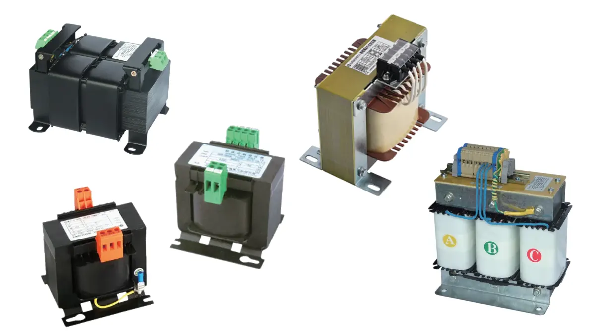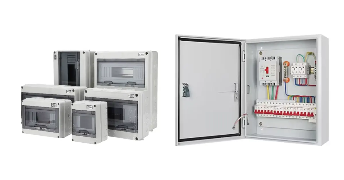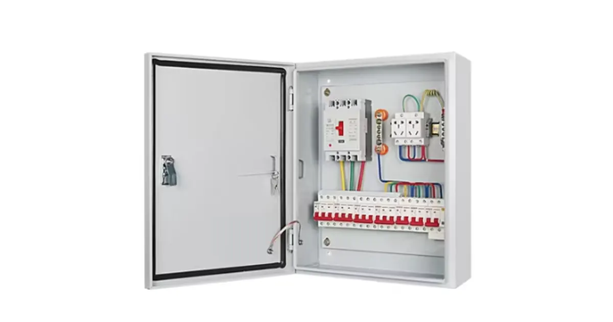
Control transformers are best classified by electrical duty, winding arrangement, construction, phase, and code category, not by output voltage alone. Most industrial control transformers are dry-type, two-winding isolation transformers designed to keep the secondary voltage stable while contactors, relays, and solenoids draw a brief but demanding inrush current.
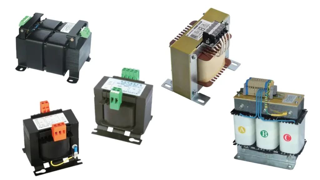
For most control panels, the practical choices are an industrial or machine-tool control transformer, a general-purpose unit, a multi-tap design, an open or encapsulated construction, and, where the circuit specifically requires it, a listed Class 2 transformer. Single-phase units are common even inside three-phase machines; you only need a three-phase control transformer when the actual auxiliary load and system design require one.
The right choice depends on five numbers before anything else: primary voltage, secondary voltage, frequency, continuous (sealed) VA, and the worst simultaneous inrush VA. The type name on its own cannot confirm that a transformer will hold the required control voltage during pickup.
What Makes a Control Transformer Different?
Voltage stability during inrush
A contactor coil may draw several times its sealed current for a few cycles while the armature closes. If the transformer voltage drops too far during that event, the coil can chatter, fail to pull in, or repeatedly restart. A control transformer is therefore judged not only by continuous VA but also by its short-duration inrush capacity and voltage-regulation data.
Galvanic isolation
In a conventional two-winding control transformer, the primary and secondary are electrically separate. This lets you derive a control voltage such as 120 VAC or 24 VAC from a higher machine supply while creating a separately derived secondary circuit. Grounding, bonding, and overcurrent protection still have to follow the transformer instructions and the electrical code that applies to the panel.
What a control transformer does not do
A transformer does not automatically make a circuit Class 2, convert AC to DC, or replace a disconnecting means. A 24 VAC secondary remains AC unless a rectifier and, where needed, regulation are added. Pushbuttons, relays, and control-circuit devices are also not energy-isolating devices for lockout/tagout.
The Main Types of Control Transformers
These categories overlap. A single transformer can be single-phase, multi-tap, encapsulated, and designed for high-inrush industrial duty at the same time. Classify the application first, then compare the electrical and mechanical details.
| Type or construction | What distinguishes it | Typical fit | What to verify |
|---|---|---|---|
| Industrial or machine-tool control transformer | Low-impedance design with published regulation or inrush performance | Contactors, motor starters, solenoids, relays, and mixed panel loads | Continuous VA and voltage during the worst simultaneous pickup event |
| General-purpose transformer | Designed for ordinary low-voltage power conversion and isolation | Steady auxiliary loads with limited inrush | Do not assume it can support coil pickup; check the load profile and regulation data |
| Multi-tap or dual-winding transformer | Multiple primary taps, secondary connections, or both | Export equipment, several nominal supply voltages, or standardized panel designs | Tap diagram, series/parallel connections, frequency, and terminal insulation |
| Open-frame panel-mount transformer | Core, coil, and terminals rely on the control enclosure for protection | Clean, dry industrial enclosures with controlled access | Enclosure protection, creepage, clearance, heat dissipation, and safe terminal spacing |
| Encapsulated or enclosed transformer | Windings are potted or placed in a protective housing | Dust, moisture, vibration, washdown exposure, or mounting outside a protected panel | The environmental rating belongs to the complete assembly, not to the resin alone |
| Class 2 listed transformer | Specifically evaluated and marked as a limited-power Class 2 source | Class 2 control, signaling, thermostat, and similar limited-power circuits | Listing, nameplate marking, voltage/current limits, and the applicable code, not simply 24 V on the label |
| Single-phase control transformer | One primary and one secondary phase relationship | Most contactor, relay, solenoid, and panel control circuits | Whether the primary is connected line-to-line or line-to-neutral, plus the resulting primary voltage |
| Three-phase control transformer | Three-phase magnetic circuit and three-phase input/output arrangement | Auxiliary loads that genuinely require three-phase power | Phase sequence, vector group where relevant, balance, and whether the control load is actually three-phase |
Single-phase vs three-phase: use the load, not the machine nameplate
A three-phase machine does not automatically need a three-phase control transformer. Many industrial panels feed a single-phase control transformer from two phases of the incoming three-phase supply. That arrangement is appropriate when the primary voltage, transformer rating, conductor protection, grounding, and panel design all match.
Choose a three-phase unit only when the downstream auxiliary load is three-phase or when the engineering design has another clear reason for it. This distinction often reduces unnecessary size, cost, and wiring complexity.
Step-down and step-up describe ratio, not duty
Most control transformers are step-down units because they derive 120 VAC, 24 VAC, or another lower control voltage from the machine supply. Step-up control applications exist, but they are less common. The ratio tells you how the voltage changes; it does not tell you whether the transformer has the inrush performance, isolation, enclosure, or approval your panel needs.
Control Transformers vs Commonly Confused Devices
Several devices may change voltage or provide isolation, but they are not interchangeable. The table below separates their primary functions.
| Device | Primary function | Can it replace an industrial control transformer? |
|---|---|---|
| Control transformer | Supply an AC control circuit and maintain usable secondary voltage during short inrush events | It is the reference choice for contactors, relays, solenoids, and similar panel loads |
| Isolation transformer | Provide galvanic separation; the voltage ratio may be 1:1 or step-up/step-down | Only if its continuous rating, regulation, inrush capability, construction, and approvals also match the control application |
| Autotransformer | Change voltage through one shared winding | Usually not a drop-in substitute because it does not provide galvanic isolation |
| Instrument transformer | Scale current or voltage for metering and protection | No. Current transformers and potential/voltage transformers are measurement devices, not control-power sources |
| General power transformer | Transfer power continuously at its rated load | Only after verifying its short-duration regulation against the control load’s pickup demand |
| AC-to-DC switching power supply | Produce regulated DC for PLCs, sensors, I/O, and electronics | Use it when the load requires DC. A transformer by itself produces AC |
If you are comparing a control transformer with a voltage-measurement device, see control power transformer vs potential transformer. Their similar voltage terminology hides very different duties.
How to Select a Control Transformer
Start with the load schedule and the panel supply. A product family name is useful only after these requirements are known.
1. Confirm primary voltage, connection, and frequency
Record the actual voltage at the intended primary connection, not only the machine’s nominal system voltage. On a three-phase system, a single-phase transformer may be connected line-to-line or, where the system permits, line-to-neutral. Those connections present different voltages. Also confirm 50 Hz, 60 Hz, or a dual-frequency rating; never assume a 60 Hz-only design can operate at 50 Hz without derating or manufacturer approval.
If the supply varies by country or facility, a multi-tap primary can simplify one panel design. The selected tap must match the incoming voltage, and unused leads must be insulated exactly as the wiring diagram requires.
2. Define the required secondary: voltage, AC or DC, and grounding
List every load and its required input. A 24 VAC contactor coil and a 24 VDC PLC input are not interchangeable. If the panel needs regulated DC, the transformer may feed a rectifier or switching power supply, but the DC supply must be sized as its own load and checked for input inrush.
Decide how the secondary will be grounded or left ungrounded under the applicable code and equipment design. A two-winding transformer provides separation; it does not decide the grounding scheme for you.
3. Calculate the continuous, or sealed, VA
Add the sealed VA of all devices that can remain energized at the same time. Use the coil or device manufacturer’s VA data whenever it is available. For a simple single-phase load, VA equals volts multiplied by amperes, but watts are not a reliable substitute when power factor is unknown.
Your selected transformer’s continuous rating must be at least the simultaneous sealed load after any required ambient, altitude, or enclosure derating. Planned additions should be included as identifiable loads rather than hidden inside an arbitrary percentage.
4. Build the worst realistic simultaneous inrush event
Identify which contactors, solenoids, relays, brakes, and power-supply inputs can start together. For each operating sequence, combine the sealed VA of loads already energized with the inrush VA of the devices picking up. Use the highest credible event.
Adding the inrush of every device in the panel can badly oversize the transformer if the devices are interlocked or sequenced. Ignoring simultaneous pickup creates the opposite problem. The control sequence, not the parts list, determines the event.
5. Use the transformer’s regulation or inrush-selection table
Do not select a 250 VA transformer merely because one event totals 225 VA. First satisfy the continuous-VA requirement, then use the supplier’s regulation table or inrush curve to confirm that a candidate model can support the event while keeping the secondary above the minimum acceptable voltage for every coil and electronic load.
Different manufacturers may use different calculation methods and regulation columns. Follow one supplier’s instructions from load calculation through final model selection; mixing a formula from one catalog with a table from another can produce the wrong result. For more detail, see Linkwell’s control transformer sizing method and control transformer rating overview.
6. Match construction to the installation
Check ambient temperature, temperature rise, insulation system, altitude, ventilation, vibration, contamination, humidity, and available panel space. An open unit may be suitable inside a protected industrial enclosure, while an encapsulated or separately enclosed unit may be preferable where dust or moisture is harder to control. Verify the complete assembly’s enclosure or ingress rating rather than inferring it from appearance.
7. Coordinate protection, wiring, and approvals
Confirm primary and secondary overcurrent protection, conductor size, terminal configuration, grounding and bonding, short-circuit ratings, and required market approvals. Some transformers include protection; others require external devices. Apply the nameplate and manufacturer instructions together with the adopted electrical code and local inspection requirements.
For UL 508A industrial control panels, component acceptance and installation conditions matter. A panel certification does not make an unsuitable transformer acceptable, and a component mark does not remove the need to follow its conditions of use.
A Practical Sizing Example
Assume a 120 VAC control circuit has 45 VA of relays, pilot devices, and other loads already energized. One contactor then starts. Its coil data lists 180 VA inrush and 15 VA sealed.
| Operating condition | Calculation | Required transformer check |
|---|---|---|
| Before the contactor starts | 45 VA sealed | Continuous load already present |
| During contactor pickup | 45 VA existing sealed + 180 VA contactor inrush = 225 VA event | Candidate must hold the required secondary voltage during this event |
| After the contactor closes | 45 VA existing + 15 VA contactor sealed = 60 VA continuous | Candidate continuous rating must be at least 60 VA after applicable derating |
You now have two separate requirements: at least 60 VA continuous capacity and enough short-duration regulation performance for a 225 VA pickup event. Use both values with the selected transformer’s own inrush table or regulation curve. A transformer’s nameplate VA alone does not tell you whether its secondary voltage will remain high enough during pickup.
If two contactors can close together, replace the single 180 VA figure with their simultaneous inrush total. If the sequence prevents that event, do not add it merely because both devices appear in the panel.
Common Selection Mistakes
- Sizing from watts instead of VA. Coil power factor and pickup behavior make watts an unreliable substitute for manufacturer VA data.
- Using only the sealed load. A transformer may run cool at steady state yet allow the secondary voltage to collapse when a contactor pulls in.
- Adding every inrush value. If devices cannot start together, this method can produce an unnecessarily large transformer with higher cost and primary energization current.
- Assuming a three-phase machine requires a three-phase control transformer. The actual control load and connection determine phase, not the motor nameplate.
- Treating 24 VAC as 24 VDC. PLCs, sensors, and electronic I/O often need regulated DC; a transformer alone supplies AC.
- Calling every low-voltage transformer Class 2. Class 2 is a listed, marked, code-defined limited-power source. Secondary voltage alone does not establish it.
- Ignoring taps, frequency, or the wiring diagram. A wrong primary connection can create the wrong secondary voltage, overheating, or equipment damage.
- Assuming the transformer provides complete circuit protection. Coordinate primary and secondary protection, conductors, grounding, and panel short-circuit requirements for the specific installation.
- Installing an open unit in a harsh location. Dust, conductive contamination, moisture, and poor ventilation change what construction and enclosure you need.
- Using the control circuit as an energy-isolation method. Open the appropriate energy-isolating device and follow the facility’s lockout/tagout procedure before service.
Choosing a Linkwell Control Transformer
Linkwell’s control transformer range includes single-phase, three-phase, and encapsulated options, with JBK5, JBK6, JSG, SG, and SGC series represented in the current portfolio. The correct series depends on your electrical load, installation environment, and target-market requirements; a series name is not a substitute for a complete specification.
Send the following information with your request so the selection can be checked before quotation:
| Required information | What to provide |
|---|---|
| Input | Primary voltage, available connection, frequency, and phase |
| Output | Required secondary voltage and whether the downstream loads require AC or DC |
| Continuous load | Total simultaneous sealed VA, with device data where available |
| Pickup event | Largest simultaneous inrush VA and the loads already energized during that event |
| Installation | Ambient temperature, altitude, enclosure, contamination, humidity, vibration, mounting, and space limits |
| Compliance | Destination country, panel standard, required marks or certifications, and any customer specification |
| Commercial details | Quantity, drawing or terminal preference, packaging, and project schedule |
Availability, taps, VA ratings, approvals, and construction vary by model. Ask for the current datasheet and wiring diagram, then confirm the selected unit against your panel’s load schedule and protection design.
Frequently Asked Questions
Can you use a single-phase control transformer on a three-phase machine?
Yes. A common arrangement connects a single-phase primary across two phases of a three-phase supply. It is suitable when the applied primary voltage, transformer rating, protection, wiring, and downstream single-phase control load all match. The fact that the machine motors are three-phase does not by itself require a three-phase control transformer.
Are all control transformers isolation transformers?
Most conventional industrial control transformers use separate primary and secondary windings and therefore provide galvanic isolation. An autotransformer uses a shared winding and does not. Check the winding diagram and product standard instead of relying only on the product name.
What makes a transformer Class 2?
A Class 2 transformer is specifically evaluated, listed, and marked for a Class 2 limited-power circuit under the applicable code and product standard. A transformer is not Class 2 simply because its secondary is 24 V or its VA rating is small.
Is 24 VAC the same as 24 VDC?
No. They have different waveforms, wiring implications, and load compatibility. A 24 VAC transformer can feed a suitable rectifier or DC power supply, but you must size and specify the complete conversion stage. Never connect a DC-only PLC input or sensor to 24 VAC unless its documentation explicitly permits it.
How much spare VA should you add?
There is no universal 20% or 25% rule that replaces a load study. Size the transformer for simultaneous sealed VA, the worst credible pickup event, required voltage regulation, environmental derating, and known future loads. Add project margin deliberately and check that the larger unit’s primary energization current remains compatible with upstream protection.
What happens if a control transformer is undersized?
During pickup, the secondary voltage may sag enough to cause coil chatter, contactor dropout, nuisance resets, or unreliable solenoid operation. Sustained overload can also raise winding temperature and shorten insulation life. Measure the voltage during the actual event and compare the load with the transformer’s regulation data before blaming the coil.
Can a control transformer be too large?
Yes. Oversizing usually costs more, occupies more panel space, and may increase primary energization current. It can also complicate protection coordination. Select enough continuous and inrush capability, but do not add all non-simultaneous pickup loads or choose a much larger unit without a design reason.
Does a control transformer need primary and secondary fuses?
Protection depends on the transformer’s listing, integral protection, conductor arrangement, installation, and adopted code. Follow the nameplate and manufacturer instructions, then coordinate external primary and secondary protection with the panel design. Do not assume that internal thermal protection covers every overcurrent or short-circuit condition.
Can a 60 Hz transformer run on 50 Hz?
Only when the manufacturer marks or approves that operation. At the same applied voltage, lower frequency increases magnetic flux and can cause excessive heating or saturation. Use a 50/60 Hz-rated model, the correct tap, or an approved derating method.
Standards and Technical References
Use the editions adopted for the destination market and verify the individual product’s certification status. The following primary references define the main safety and panel context discussed above:
- IEC 61558-2-2:2022 – particular requirements and tests for control transformers and power supply units incorporating control transformers.
- UL 5085-1 – general requirements for low-voltage transformers.
- UL 5085-3 – requirements for Class 2 and Class 3 transformers.
- UL 508A Supplement SA guidance – component requirements in industrial control panels.
- OSHA control of hazardous energy – lockout/tagout requirements and the distinction between control devices and energy-isolating devices.
These references help define the category and installation context; they do not prove that a particular transformer model is certified. Confirm the current certificate, scope, nameplate, and conditions of use for the exact part number.
Get the Specification Right Before You Order
A useful transformer recommendation starts with the operating sequence, not a preferred VA size. Send Linkwell your primary and secondary requirements, frequency, simultaneous sealed VA, worst pickup event, installation environment, and target-market approvals. We can then review the suitable series and supply the current datasheet, dimensions, terminal information, and wiring diagram for your project.