
What exactly are amps in electricity? Simply put, amps, or amperes, measure the rate of electrical current flow. Think of it like the amount of water flowing through a pipe in a given time. A higher amperage means more electrons are moving through a conductor per second, indicating a greater electrical current.
For beginners venturing into the world of electricity, understanding amps is fundamental. It helps in grasping how much electrical power is being used or delivered. Along with voltage (electrical pressure) and resistance (opposition to flow), amperage forms a cornerstone of basic electrical concepts.
What is Amps in Electricity?
In electricity, amps (amperes) are the unit used to measure the rate of electrical current flow. Think of it like the amount of water flowing through a pipe in a given time. One amp is defined as one coulomb of electrical charge (which is 6.241×10¹⁸ electrons) moving past a point in one second.
Amps describe the intensity of the electrical current. A higher amperage means more electrons are flowing through a conductor. This is crucial for understanding the power requirements of devices and the capacity of electrical circuits. Too much current flowing through a wire can cause it to overheat, potentially leading to fires, which is why circuit breakers are designed to trip when the current exceeds a safe level (measured in amps).
Wire Size Amp Rating
Understanding the relationship between wire size and its amp rating is fundamental to electrical safety and functionality. The American Wire Gauge (AWG) system standardizes wire diameters, with smaller gauge numbers indicating thicker wires.
A wire’s thickness directly impacts its ability to safely carry electrical current; thicker wires offer less resistance, allowing for higher ampacities without overheating. Selecting the correct wire size for a given current load is crucial to prevent potential fire hazards and ensure efficient power delivery.
Wire Gauge and Diameter
The American Wire Gauge (AWG) is a logarithmic stepped standard that defines wire sizes. It might seem counterintuitive, but a lower AWG number signifies a larger diameter wire. For instance, a 12 AWG wire is thicker than a 14 AWG wire.
This difference in diameter directly affects the wire’s cross-sectional area, which in turn dictates how much current it can safely conduct. Knowing the AWG of a wire is the first step in determining its appropriate amp rating for a specific application.
Ampacity and Safety
Ampacity refers to the maximum amount of electrical current, in amperes, that a conductor can carry continuously under specific conditions without exceeding its temperature rating. This rating is not a fixed number for a given wire gauge but is influenced by factors like the wire’s insulation type, the ambient temperature, and whether the wire is bundled with others or run in conduit.
Exceeding a wire’s ampacity can lead to excessive heat buildup, potentially melting the insulation and causing short circuits or fires. Electrical codes provide tables and guidelines to ensure the correct wire size is chosen based on the expected current load and installation environment.
Factors Affecting Amp Rating
Several factors influence a wire’s safe amp rating beyond just its gauge. The insulation material plays a significant role, as different materials can withstand varying temperatures. Higher temperature-rated insulations generally allow for higher ampacities. The ambient temperature of the surroundings also affects heat dissipation; hotter environments reduce a wire’s ability to cool, thus lowering its ampacity.
Additionally, the way wires are installed matters. Wires run in open air can dissipate heat more effectively than those enclosed in conduits or bundled together, which can restrict airflow and reduce ampacity. Therefore, consulting ampacity tables that consider these conditions is essential for safe electrical installations.
Amps vs. Volts, Ohms, and Watts
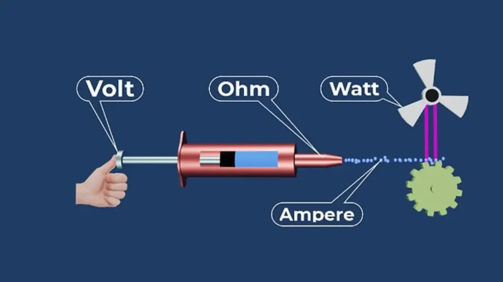
Understanding the fundamental concepts of amps, volts, ohms, and watts is essential for anyone working with or simply trying to comprehend electrical circuits. These four units are interconnected and describe different aspects of electrical energy.
Amps measure the flow rate of electrical charge, volts represent the electrical potential difference or pressure, ohms quantify the resistance to this flow, and watts measure the rate at which energy is transferred or used. Grasping their individual meanings and how they relate to each other through Ohm’s Law and the power formula provides a solid foundation for electrical knowledge.
Amps (I)
Amps, short for amperes and denoted by the letter ‘I’ in formulas, quantify the electrical current. Think of it as the volume of water flowing through a pipe. One amp represents one coulomb of electrical charge passing a point in one second. Therefore, amperage indicates the rate at which electrons are moving through a conductor. A higher amp value signifies a greater flow of electrical charge.
Volts (V or E)
Volts, symbolized by ‘V’ or sometimes ‘E’ (for electromotive force), measure the electrical potential difference between two points in a circuit. This is analogous to the water pressure in a pipe, which drives the flow of water. One volt is the potential difference needed to cause one amp of current to flow through a resistance of one ohm. Voltage is the force that pushes the electrons through the circuit.
Ohms (Ω or R)
Ohms, represented by the Greek letter omega ‘Ω’ or the letter ‘R’, measure electrical resistance. Resistance is the opposition to the flow of electrical current within a circuit. Using the water analogy, resistance would be the narrowness or roughness of the pipe, hindering water flow. One ohm is the resistance when a potential difference of one volt applied across a conductor produces a current of one amp.
Watts (P)
Watts, abbreviated as ‘W’ and denoted by ‘P’ for power, measure the rate of energy transfer or consumption. In our water analogy, watts would represent the rate at which the water wheel at the end of the pipe is turning, indicating the power being delivered. One watt is equal to one joule of energy per second. Electrically, power in a DC circuit is calculated by multiplying the voltage (in volts) by the current (in amps).
How to Calculate Amps
To calculate amps (amperes), which is the unit for electric current, you typically use two fundamental relationships in electricity:
- Ohm’s Law: Relates current, voltage, and resistance.
- Power Formula: Relates current, power, and voltage.
Let’s break down how to calculate amps using each of these.
1. Using Ohm’s Law (When you know Voltage and Resistance)
Ohm’s Law states the relationship between voltage (V), current (I), and resistance (R).
Formula: I=RV
Where:
- I = Current in Amperes (A)
- V = Voltage in Volts (V)
- R = Resistance in Ohms (Ω)
Explanation: This formula tells us that the current (amps) flowing through a circuit is directly proportional to the voltage applied across it and inversely proportional to the resistance of the circuit. In simpler terms:
- Higher voltage means more current (if resistance stays the same).
- Higher resistance means less current (if voltage stays the same).
Example: If you have a circuit with a 12-volt battery and a 4-ohm resistor: I=4Ω12V I=3A
So, the current flowing through the circuit is 3 amps.
2. Using the Power Formula (When you know Power and Voltage)
The power formula (also known as Joule’s Law) relates power (P), current (I), and voltage (V).
Formula: I=VP
Where:
- I = Current in Amperes (A)
- P = Power in Watts (W)
- V = Voltage in Volts (V)
Explanation: This formula is very commonly used for household appliances and determining how much current a device will draw. Power (watts) is the rate at which electrical energy is consumed or produced.
Example: If you have a 60-watt light bulb plugged into a 120-volt outlet: I=120V60W I=0.5A
So, the light bulb draws 0.5 amps of current.
Important Note for AC Circuits: For Alternating Current (AC) circuits, especially with inductive or capacitive loads (like motors or fluorescent lights), a concept called power factor (PF) comes into play. In these cases, the formula becomes:
I=V×PFP
- PF (Power Factor) is a value between 0 and 1 (or 0% and 100%). For purely resistive loads (like a simple incandescent light bulb or a heating element), the power factor is 1. For motors, it can be significantly less than 1. If the power factor is not given, it is often assumed to be 1 for simplicity or for basic resistive loads.
Summary of Formulas to Calculate Amps:
- If you know Voltage (V) and Resistance (R): I=RV (Ohm’s Law)
- If you know Power (P) and Voltage (V): I=VP (For DC circuits or purely resistive AC circuits) I=V×PFP (For AC circuits with power factor)
Remember to always use consistent units (Volts, Ohms, Watts, Amps) for your calculations.
Calculating Load for Industrial Control Cabinets
First, list all electrical devices installed in the cabinet, such as PLCs, power supplies, contactors, relays, VFDs, HMIs, fans, and auxiliary modules. For each device, identify its rated power consumption in watts (W) or current in amperes (A), using the manufacturer’s datasheet. If current is given, convert it to power using the formula P = V × I. Next, add the power values of all devices to obtain the total cabinet load. For components with inrush or peak current, such as transformers or motors, include their maximum demand. Then apply a safety margin of 20–30% to allow for future expansion and stable operation.
The calculated load is used to size power supplies, circuit breakers, wiring, and grounding, and to determine cooling requirements. Accurate load calculation prevents overheating, nuisance tripping, and premature component failure in industrial control cabinets.
Conclusion
In conclusion, amps measure the rate of electrical current flow, akin to the volume of water in a pipe. Understanding amperage is fundamental for comprehending how much electricity a device uses and ensuring circuit safety.
For reliable wholesale electric components to manage this current effectively in your projects, consider sourcing from trusted suppliers from Linkwell Electrics. We will offer a range of quality electrical component products to meet your electrical needs.